


 русский
 Español
Heat treatment is a controlled thermal process that changes the mechanical properties of metal by heating it to a specific temperature, holding it there, and then cooling it at a rate chosen to produce a desired internal structur...
READ MORE
What Does CNC Stand For? Understanding CNC Equipment
Content
- 1 What Does CNC Stand For?
- 2 From Punched Tape to Modern Controllers
- 3 How a CNC Machine Actually Turns a Design Into a Part
- 4 Understanding CNC Axes: 3-Axis, 4-Axis, and 5-Axis
- 5 Common Types of CNC Equipment
- 6 CNC Controllers and Programming Languages
- 7 Cutting Tools and Workholding for CNC Equipment
- 8 Precision: What Tolerances Can CNC Equipment Actually Hold?
- 9 Materials CNC Equipment Can Process
- 10 CNC Machining vs. Manual Machining
- 11 What Drives the Cost of CNC Machining
- 12 Which Industries Rely on CNC Equipment
- 13 Quality Control and Inspection for CNC-Machined Parts
- 14 Keeping CNC Equipment Running: Basic Maintenance
- 15 Choosing the Right CNC Equipment for a Job
- 16 CNC Terms Worth Knowing
- 17 Frequently Asked Questions About CNC
- 17.1 Does CNC always mean the same thing as a machining center?
- 17.2 Is CNC the same as 3D printing?
- 17.3 What does G-code have to do with CNC?
- 17.4 How accurate is CNC machining compared to 3D printing?
- 17.5 Can CNC machines run without an operator present?
- 17.6 What is the difference between NC and CNC?
- 17.7 Why would a shop choose a 5-axis machine over a 3-axis machine?
- 17.8 What is the difference between a CNC mill and a CNC router?
- 17.9 How long does it take to program a CNC job?
- 17.10 Does CNC machining produce waste material?
What Does CNC Stand For?
CNC stands for Computer Numerical Control. It describes any machine tool whose cutting motions, spindle speed, and toolpath are directed by a computer program rather than by a person turning handwheels or levers. When a shop says it runs CNC Equipment, it means the mills, lathes, routers, and grinders on the floor are guided by pre-written code that tells each axis exactly where to move, how fast to move, and when to stop.
The "numerical" part of the name comes from how the instructions are written: as a sequence of numbers and coordinates, most commonly in a format called G-code. A program might read something like G01 X50.0 Y25.0 F150, which tells the machine to move in a straight line to a specific X-Y position at a defined feed rate. The controller reads that line, translates it into motor commands, and the machine executes it with repeatable accuracy that a human hand cannot match over long production runs.
It helps to separate two related but distinct terms. CNC machining is the process, the act of removing material under computer control to shape a part. CNC Equipment, or a CNC machine, is the physical hardware that carries out that process. A shop can own a wide range of CNC Equipment, mills, lathes, grinders, EDM units, and each one applies the same underlying control philosophy to a different type of cutting motion.
From Punched Tape to Modern Controllers
Numerical control did not start with computers at all. In the 1940s and 1950s, early NC machines were guided by punched paper tape, with each hole pattern corresponding to a specific instruction. Changing a program meant physically producing a new tape, which was slow and fragile, and a single torn section could stop a production run for hours while a replacement was cut.
The shift to Computer Numerical Control in the 1970s replaced that tape with onboard computer memory, letting operators edit programs directly at the machine and store multiple jobs for reuse. This period also introduced Direct Numerical Control, where a central computer distributed programs to several machines on a shop floor over a network, removing the need to carry tape or a removable disk from machine to machine.
Why the shift mattered
Once programs lived in computer memory instead of on tape, manufacturers could make small edits without recreating an entire program, run simulations before cutting real material, and network machines together so a single design file could be sent to several pieces of CNC Equipment at once. That combination of flexibility and repeatability is why CNC replaced manual and basic NC machining across most of the industrial world within a couple of decades.
Where the technology stands today
Modern controllers add features that early CNC systems never had, including graphical program verification on-screen, automatic tool-length measurement, and network connections that let a program move from a design workstation to the machine floor without ever being carried on physical media. The core principle, however, is unchanged: numbers in a program file translate directly into physical motion on the shop floor.
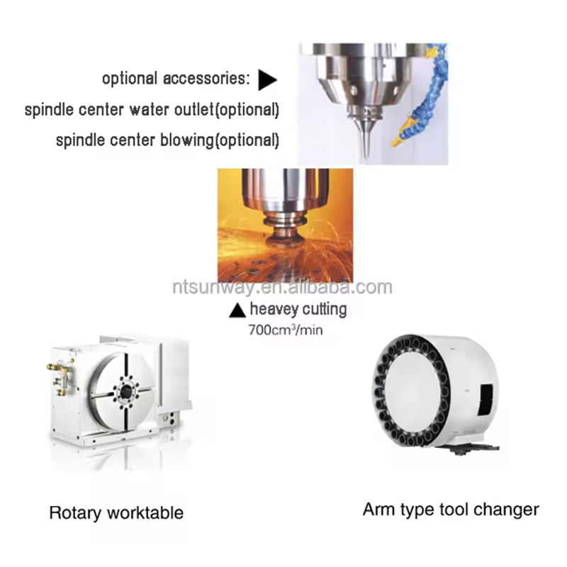
How a CNC Machine Actually Turns a Design Into a Part
The path from an idea to a finished part follows a consistent sequence, regardless of whether the machine is a small desktop router or an industrial five-axis machining center.
- A designer creates a 3D model in CAD (computer-aided design) software.
- CAM (computer-aided manufacturing) software converts that model into a toolpath, choosing which cutting tools to use and in what order.
- The CAM software generates G-code, the numerical instruction set the machine controller can read.
- An operator loads the code, sets up the raw material (called the blank or workpiece), and installs the correct tooling.
- The machine runs a dry cycle, without the workpiece in place, to confirm the toolpath is correct and safe.
- Production begins, with the controller directing spindle speed, feed rate, and axis movement for every cut.
- The finished part is measured against the drawing to confirm it falls within the required tolerance before it moves to the next process.
Cutting speed is typically measured in surface feet per minute, while feed rate describes how quickly the tool advances through the material. Both values are programmed in advance and rarely require manual adjustment once a job is dialed in, which is a large part of why CNC Equipment produces consistent parts from the first piece to the thousandth.
Programmers also account for tool wear during long runs. As a cutting edge dulls, it can change the size of the feature it cuts by a small but measurable amount, so many programs include scheduled tool changes or wear offsets that compensate automatically before a part drifts out of tolerance.
Understanding CNC Axes: 3-Axis, 4-Axis, and 5-Axis
The number of axes a machine has describes how many independent directions the cutting tool and workpiece can move relative to each other, and it has a direct effect on what geometry a single piece of CNC Equipment can produce without repositioning the part by hand.
| Configuration | Motion | Best Suited For |
|---|---|---|
| 3-Axis | Linear movement along X, Y, and Z | Flat faces, pockets, drilled holes |
| 4-Axis | X, Y, Z plus rotation on the A-axis | Angled features, cam profiles, cylindrical detail |
| 5-Axis | X, Y, Z plus two rotational axes | Complex curved surfaces, undercuts, single-setup parts |
A 3-axis machine moves the cutting tool along three straight lines, side to side, front to back, and up and down. It is the most common configuration because it is the least expensive to buy and the simplest to program, and it covers a large share of everyday parts such as brackets, plates, and housings.
A 4-axis machine adds a rotary A-axis that turns the workpiece around one of the linear axes. This lets the machine cut features on multiple sides of a part, or cut arcs and helixes, without the operator unclamping and repositioning the piece. Four-axis motion can run in indexing mode, where the rotation pauses while cutting happens, or in continuous mode, where the rotation and the cut happen at the same time.
A 5-axis machine adds a second rotational axis so the spindle or the workpiece can approach a surface from nearly any angle in one setup. This is what makes it possible to machine complex curved surfaces, deep pockets with sloped walls, and undercuts that would otherwise require multiple fixtures. Five-axis CNC Equipment generally finishes complex parts faster than 3-axis machines because it eliminates the repeated unclamping, realigning, and re-zeroing that multiple setups require, though the tradeoff is a steeper programming curve and a higher machine cost.
Common Types of CNC Equipment
CNC is not a single machine; it is a control method applied across many different machine tool categories. The table below outlines the equipment types found in most production shops.
| Equipment Type | Primary Motion | Typical Use |
|---|---|---|
| CNC Mill | Rotating cutter, moving table | Flat surfaces, pockets, slots, holes |
| CNC Lathe | Rotating workpiece, stationary cutter | Cylindrical and round parts |
| Swiss-Type Lathe | Sliding headstock, guide bushing | Small, slender, high-precision turned parts |
| CNC Router | Rotating cutter over flat stock | Wood, plastic, soft metal sheet cutting |
| CNC Grinder | Abrasive wheel contact | Fine surface finishing, tight tolerances |
| Wire EDM | Electrical discharge through wire | Hardened metals, intricate internal shapes |
| CNC Laser or Plasma Cutter | Focused beam or arc | Sheet metal profiling and cutting |
| Multi-Tasking Machine | Combined milling and turning | Complex parts in a single setup |
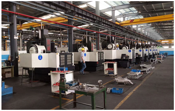
Multi-axis machining centers combine several of these motions into one machine. A five-axis mill, for example, can rotate the workpiece on two additional axes while the cutting tool moves along the standard three, allowing a single setup to reach angled and undercut surfaces that would otherwise require repositioning the part by hand. Multi-tasking machines take this further by combining a lathe's turning spindle with a mill's rotating cutter in one unit, so a part can be turned, drilled, and milled without ever being moved to a second machine.
CNC Controllers and Programming Languages
The controller is the onboard computer that reads a program and converts it into motor commands. Several controller brands dominate industrial shops, and while they share the same underlying G-code standard, each has its own dialect and screen interface.
- G-code: the core movement language, where each line beginning with G specifies a type of motion, such as a rapid move, a linear cut, or a circular arc
- M-code: miscellaneous function commands that control machine functions outside of motion, such as starting the spindle, turning on coolant, or changing a tool
- Canned cycles: shorthand programming blocks that repeat common operations, such as drilling a pattern of holes, without writing out every individual move
Operators rarely write long programs by hand today. Instead, CAM software generates the G-code automatically from a 3D model, and the operator reviews or fine-tunes it before running the job. Hand-written G-code is still common for simple parts, quick edits on the shop floor, or teaching new operators how the underlying language works.
Cutting Tools and Workholding for CNC Equipment
Common cutting tools
The tool actually doing the cutting is chosen based on the material, the feature being cut, and the finish required. End mills remove material from the side and bottom of a pocket or profile. Drills create round holes. Taps cut internal threads. Face mills clear large flat areas quickly. Inserts, small replaceable cutting tips mounted in a tool holder, are common on lathes and heavy-duty mills because a worn insert can be swapped without replacing the entire tool.
Workholding and fixturing
Before a program runs, the workpiece has to be held securely enough to resist cutting forces without deforming the part or letting it shift position. Common workholding methods include vises, which clamp flat or rectangular stock from the sides; chucks, which grip round stock on a lathe; and custom fixtures, machined specifically to hold one part design in a repeatable location for high-volume runs. Soft jaws, machined to match a specific part's contour, are common when a standard vise would mark or distort a delicate surface.
Workholding choice affects both accuracy and cycle time. A fixture that lets an operator load and unload a part in seconds, rather than minutes, has a direct effect on how many parts a shop can produce per shift, which is why fixture design gets serious attention on any job running in meaningful volume.
Precision: What Tolerances Can CNC Equipment Actually Hold?
Tolerance is the allowable variation between the intended dimension on a drawing and the dimension on the finished part. General-purpose CNC Equipment commonly holds tolerances around ±0.005 in (about 0.127 mm), roughly twice the width of a human hair. Precision machining centers built for aerospace or medical work can hold considerably tighter tolerances, sometimes down to ±0.0004 in (about 0.01 mm), though achieving that level typically requires slower feed rates, rigid fixturing, and controlled shop temperature.
Several factors influence how tight a tolerance a given job can realistically hold, including the rigidity of the machine itself, the sharpness and condition of the cutting tool, the thermal stability of the shop environment, and how securely the part is held during the cut. A machine capable of ±0.0004 in on a small, rigid part may not hold that same tolerance on a long, thin part prone to flexing under cutting pressure.
Not every feature on a part needs the tightest possible tolerance. Specifying a tight tolerance only where two parts actually mate or move against each other, and leaving looser tolerances elsewhere, keeps machining time and cost reasonable without sacrificing function. Over-specifying tolerance across an entire drawing is one of the most common reasons a machining quote comes back higher than expected.
Materials CNC Equipment Can Process
One reason CNC adoption spread so widely is that the same control method works across a broad range of materials, with the machine and tooling changed to suit the job rather than the fundamental process changing.
- Metals: aluminum, mild steel, stainless steel, titanium, brass, and copper alloys
- Plastics: acetal, nylon, polycarbonate, PEEK, and ABS
- Wood and engineered wood products
- Composites, including carbon fiber and fiberglass laminates
- Foam and modeling materials used for prototypes and patterns
- Glass and ceramics, typically cut with specialized abrasive or laser-based CNC Equipment
Material choice affects nearly every setting on the machine, including spindle speed, feed rate, and the coating applied to the cutting tool, which is why a program written for aluminum cannot simply be reused on titanium without adjustment. Titanium, for example, retains heat at the cutting edge far more than aluminum does, so machinists typically run it at slower speeds with heavier coolant flow to protect both the tool and the part's surface finish.
CNC Machining vs. Manual Machining
| Factor | CNC Machining | Manual Machining |
|---|---|---|
| Repeatability | Consistent across large runs | Varies by operator skill and fatigue |
| Setup time | Higher upfront programming time | Lower upfront, higher per-part time |
| Complex geometry | Handles contours and multi-axis shapes readily | Limited by operator dexterity |
| Labor during the cut | Machine runs largely unattended | Requires continuous operator control |
| Best fit | Medium to high volume, tight tolerances | One-off, simple, or repair work |
Manual machining is not obsolete; it remains useful for one-off repairs, quick prototypes, and jobs where the cost of programming a CNC job would outweigh the benefit. But for anything produced in volume, or where dimensions must repeat exactly across hundreds or thousands of parts, CNC Equipment is the standard choice across nearly every industrial sector.
What Drives the Cost of CNC Machining
Machining quotes are rarely based on a single number; several factors combine to determine the final price of a part.
- Material cost and machinability: harder materials cut more slowly and wear tools faster, raising both time and tooling cost
- Part complexity: features requiring multiple setups, tight tolerances, or specialty tooling add programming and cycle time
- Order volume: programming and fixture costs are spread across more parts as volume rises, lowering the per-part price
- Surface finish requirements: a fine finish often means slower feed rates or a secondary grinding or polishing step
- Machine type: a five-axis machining center typically carries a higher hourly rate than a basic 3-axis mill
Designers can often reduce cost meaningfully by relaxing unnecessary tolerances, standardizing hole sizes to common drill diameters, and avoiding deep, narrow pockets that require long, slender tools prone to breaking or deflecting.
Which Industries Rely on CNC Equipment
CNC machining sits behind products in nearly every sector that requires precisely shaped metal, plastic, or composite parts.
Aerospace and defense
Aircraft structural components and engine parts often carry tolerance requirements tighter than general industrial work, along with strict material traceability, making CNC Equipment with closed-loop feedback essential.
Medical devices
Surgical instruments, implants, and diagnostic equipment housings depend on CNC machining for both dimensional accuracy and the ability to work with biocompatible materials such as titanium and certain stainless steel grades.
Automotive
Engine blocks, transmission housings, and custom tooling all rely on CNC machining centers, often running continuously across multiple shifts to keep pace with production schedules.
Electronics and semiconductor equipment
Enclosures, heat sinks, and precision fixtures used in chip manufacturing require the fine surface finishes and tight tolerances that CNC Equipment is built to deliver.
Energy and industrial equipment
Valve bodies, turbine components, and pump housings used in oil, gas, and power generation are frequently machined from tough alloys that demand rigid, high-horsepower CNC Equipment to cut efficiently.
Consumer products and furniture
CNC routers shape everything from cabinet panels and furniture components to product enclosures, offering the same repeatable accuracy at a scale and cost suited to lighter materials like wood, plastic, and thin aluminum.
Quality Control and Inspection for CNC-Machined Parts
Producing a part on CNC Equipment is only half the process; confirming it actually meets the drawing is the other half. Common inspection methods include calipers and micrometers for quick manual checks, height gauges for stepped features, and coordinate measuring machines, often called CMMs, which use a touch probe to record precise 3D points across a part's surface and compare them against the CAD model.
For high-volume runs, shops frequently inspect a sample of parts at set intervals throughout a production run rather than checking every single piece, using statistical process control to catch a tool wearing out or a fixture shifting before it produces a batch of out-of-tolerance parts.
Keeping CNC Equipment Running: Basic Maintenance
Like any precision machinery, CNC Equipment performs best when it is maintained on a consistent schedule rather than run until something fails.
- Way and ball-screw lubrication, which keeps moving axes running smoothly and prevents premature wear
- Coolant system checks, since contaminated or depleted coolant shortens tool life and can affect surface finish
- Spindle and bearing inspection, to catch early signs of wear before they affect accuracy
- Periodic calibration and ballbar testing, which verifies that the machine's actual movement still matches its programmed movement
Shops that follow a documented maintenance schedule generally see fewer unplanned breakdowns and hold tighter tolerances over the life of the machine than shops that only address problems after they appear.
Choosing the Right CNC Equipment for a Job
Selecting equipment for a specific part comes down to matching machine capability to the part's geometry, material, and volume rather than picking the most advanced machine available.
- Part shape: rotational parts generally point toward a lathe, while parts with flat faces and pockets point toward a mill
- Number of setups: a five-axis machine can reduce repositioning, which improves both accuracy and cycle time on complex parts
- Material hardness: hardened tool steels may call for wire EDM instead of conventional cutting
- Production volume: low-volume prototypes may not justify extensive fixture design, while high-volume runs benefit from investing in dedicated tooling
- Finish requirements: parts needing a mirror-smooth surface may require a grinding pass in addition to milling or turning
Shops that keep a mixed fleet of mills, lathes, and grinders are typically able to route a wider range of part designs without outsourcing, which shortens lead times and keeps quality control in one place.
CNC Terms Worth Knowing
| Term | Meaning |
|---|---|
| Workpiece | The raw block or bar of material being machined into a part |
| Toolpath | The route a cutting tool follows through the material |
| Feed rate | The speed at which the tool advances through the material |
| Spindle speed | How fast the cutting tool or workpiece rotates, in RPM |
| Tolerance | The allowable dimensional variation from the drawing |
| Fixture | A custom device used to hold a part in a repeatable position |
Frequently Asked Questions About CNC
Does CNC always mean the same thing as a machining center?
Not exactly. CNC describes the control method, while a machining center is a specific type of CNC Equipment, typically a mill, that can perform several operations such as drilling, tapping, and contouring in one setup. Many CNC machines are not machining centers; a simple CNC router, for example, uses the same control principle without the multi-operation tool changer.
Is CNC the same as 3D printing?
No. CNC machining is subtractive, meaning it removes material from a solid block to reveal the final shape. 3D printing is additive, building a part layer by layer from raw material. Both are computer-controlled, but the underlying process is opposite.
What does G-code have to do with CNC?
G-code is the programming language most CNC controllers read to execute movements. Each line specifies an action, such as a linear move, an arc, or a tool change, along with the coordinates and speed needed to carry it out.
How accurate is CNC machining compared to 3D printing?
General CNC Equipment typically holds tolerances around ±0.005 in, and precision machines can go tighter still. Most desktop and mid-range 3D printers hold looser tolerances, which is one reason CNC remains the preferred method for parts that must fit precisely with other components.
Can CNC machines run without an operator present?
Many CNC machines can run unattended for a portion of a cycle once set up correctly, particularly with automated tool changers and bar feeders. However, most shops still keep an operator nearby to monitor tool wear, check part quality, and respond to alarms.
What is the difference between NC and CNC?
NC, or numerical control, refers to the original method of directing machine tools using punched tape or cards. CNC replaced that hardware-based method with onboard computer memory, allowing programs to be edited, stored, and reused without producing new physical media each time.
Why would a shop choose a 5-axis machine over a 3-axis machine?
A 5-axis machine can reach a part from nearly any angle in a single setup, which reduces the number of times a part has to be unclamped and repositioned. This generally cuts total cycle time and improves accuracy on complex geometry, though it comes with a higher machine cost and a steeper programming learning curve.
What is the difference between a CNC mill and a CNC router?
Both use a rotating cutter, but mills are generally built with heavier frames for cutting metal and holding tighter tolerances, while routers are optimized for faster movement across large, flat sheets of wood, plastic, or foam.
How long does it take to program a CNC job?
Programming time depends heavily on part complexity. A simple bracket might take a CAM programmer only minutes to set up, while a complex five-axis part with tight tolerances can take hours of toolpath planning and simulation before the first cut is ever made.
Does CNC machining produce waste material?
Yes, because it is a subtractive process, the material removed from the workpiece becomes chips or scrap. Many shops collect and recycle metal chips, and coolant systems are typically designed to separate and reclaim usable coolant from the swarf produced during cutting.
PREV:Precision CNC Milling: Tolerances, Gantry Machines & Cost Guide
NEXT:What Is CNC Programming? Complete Guide + Gantry Milling
NEXT:What Is CNC Programming? Complete Guide + Gantry Milling
Interested in cooperation or have questions?
News
-
-
An EDM machine, also called an electrical discharge machining machine, uses controlled sparks to erode electrically conductive metal without direct contact between the tool and the workpiece. The workpiece is submerged in a diele...
READ MORE -
Cutting Tools Are Used to Convert Raw Material into Functional Parts Cutting tools are the hardened, wear-resistant elements that shear away unwanted material from a workpiece to create a finished component. They are applied in e...
READ MORE -
A CNC machine can cut, drill, mill, turn, burn, and shape almost any conductive or composite material with an accuracy that manual machines rarely match. The real question is not what a CNC machine can do in theory, but what a sp...
READ MORE
Related Products

-
Factory Address
Zhaxi Township Industrial Park, Nantong City, Jiangsu Province, China (west of Huaneng Power Plant)
-
Phone
+86-13615235768
+86-15950816906
-
Fax
+86-513-85632766
-
Email
pan.director@sunwayer.com
Stay Connected
lf you can't find the answer you're looking for, chat with our friendly team.
Stay Connected
Copyright © Nantong Sunway Science and Technology Development Co., Ltd. All Rights Reserved.
China CNC Equipment Manufacturers
Custom CNC Equipment Factory
