


 русский
 Español
Heat treatment is a controlled thermal process that changes the mechanical properties of metal by heating it to a specific temperature, holding it there, and then cooling it at a rate chosen to produce a desired internal structur...
READ MORE
Precision CNC Milling: Tolerances, Gantry Machines & Cost Guide
Content
- 1 What Precision CNC Milling Actually Means in Practice
- 2 Tolerance Grades and What Each One Is Actually Good For
- 3 Surface Finish Targets and What They Cost
- 4 How a CNC Gantry Milling Machine Holds Precision on Large Workpieces
- 5 Material Behavior Under the Cutting Tool
- 6 Workholding and Fixturing for Repeatable Precision
- 7 Why Tighter Tolerance and Finish Add Cycle Time, Not Just Cost
- 8 Verifying Precision After the Part Comes Off the Machine
- 9 How Different Industries Apply These Tolerances
- 10 Cost Factors Buyers Should Actually Weigh
- 11 Matching the Process to the Part Instead of the Other Way Around
- 12 Frequently Asked Questions
- 12.1 What is considered a standard tolerance for CNC milling?
- 12.2 How tight can a CNC gantry milling machine actually hold tolerance on a large part?
- 12.3 Is milling or turning better for holding tight tolerance?
- 12.4 Why does tightening tolerance increase the price so much?
- 12.5 Do all dimensions on a part need the same tolerance grade?
- 12.6 What Ra value should a typical precision part target?
- 12.7 What materials are easiest to hold tight tolerance on?
- 12.8 How does workholding affect precision on large parts?
- 12.9 Why do five-axis gantry machines matter for large contoured parts?
- 12.10 How is precision verified after machining is complete?
What Precision CNC Milling Actually Means in Practice
Precision CNC milling is the process of removing material from a workpiece with a rotating cutting tool under computer-guided motion control, held to dimensional tolerances tighter than general-purpose machining. The plain answer most buyers are looking for: standard CNC milling holds around plus or minus 0.125 millimeters (0.005 inch), while precision milling programs routinely hold plus or minus 0.025 millimeters (0.001 inch) or better on critical features, and tight-tolerance work for aerospace, medical, and optical components can reach plus or minus 0.0025 to 0.005 millimeters on select surfaces.
Those numbers are not arbitrary. They come from a combination of machine rigidity, cutting tool deflection, thermal stability in the shop, and how the part is fixtured. A part machined on a small three-axis vertical mill and a part machined on a large gantry-style CNC milling machine can both be called precision work, but the engineering behind holding tolerance changes considerably once the workpiece grows from centimeters to meters.
Tolerance is only one half of the precision equation. The other half is surface finish, which describes the microscopic texture left behind by the cutting tool rather than the overall size of the part. A feature can sit perfectly within its dimensional tolerance and still fail in service if the surface texture is wrong for the application, which is why serious precision milling conversations always cover both topics together rather than tolerance alone.
This guide works through tolerance grades, surface finish targets, how large-format equipment such as a CNC Gantry Milling Machine holds precision across meter-scale travels, material behavior under the cutting tool, workholding and toolpath strategy, industry-specific applications, and the practical cost and quality control decisions that shape a milling project from quote to finished part.
Tolerance Grades and What Each One Is Actually Good For
Machining tolerance describes the allowable deviation from a nominal dimension, expressed as a bilateral value such as plus or minus 0.05 millimeters, a unilateral value such as plus 0.1 and minus 0 millimeters, or a limit tolerance written as a range between two numbers. Most shops default to ISO 2768 medium grade when a drawing does not call out a specific tolerance, which lines up closely with standard CNC milling capability. Moving into precision or tight-tolerance grades brings noticeably higher setup and inspection cost, so matching the grade to the feature's actual function matters more than defaulting to the tightest number available.
Geometric dimensioning and tolerancing, usually shortened to GD&T, goes a step further than a simple plus or minus figure. Instead of only constraining size, it constrains form, orientation, and position using a standardized symbolic language, which lets a designer call out flatness, perpendicularity, or position independently of the basic dimension. A part can be within its linear tolerance and still fail a GD&T callout if a surface is not flat enough or a hole is not positioned correctly relative to a datum, so complex assemblies increasingly rely on GD&T rather than dimensional tolerance alone.
| Tolerance Grade | Typical Dimensional Tolerance | Where It Is Normally Applied |
|---|---|---|
| Standard (ISO 2768-m) | ±0.125 mm (±0.005 in) | Brackets, housings, non-mating structural parts |
| Precision | ±0.025 mm (±0.001 in) | Mating surfaces, locating pins, gearbox faces |
| Tight tolerance | ±0.005 mm to ±0.0125 mm | Bearing seats, sealing interfaces, press fits |
| Ultra-precision | ±0.0025 mm or tighter | Medical implants, aerospace flight-critical components, optics fixtures |
A useful rule engineers keep coming back to: apply tight tolerance only where the feature's function actually depends on it, such as a bearing bore or a sealing face, and leave the rest of the part at standard grade. This single decision often has more effect on final cost than the choice of material or machine.
Reading a Tolerance Callout Correctly
A bilateral tolerance such as plus or minus 0.05 millimeters allows deviation in either direction from the nominal size. A unilateral tolerance, written as plus 0.1 and minus 0 millimeters, only allows growth in one direction, which is common on features that will later be reamed or ground to final size. A limit tolerance simply states the maximum and minimum acceptable dimension directly, such as 10.1 millimeters to 9.9 millimeters, which removes any ambiguity about which direction the deviation runs. Reading these correctly at the quoting stage avoids a surprising number of disputes later in production.
Surface Finish Targets and What They Cost
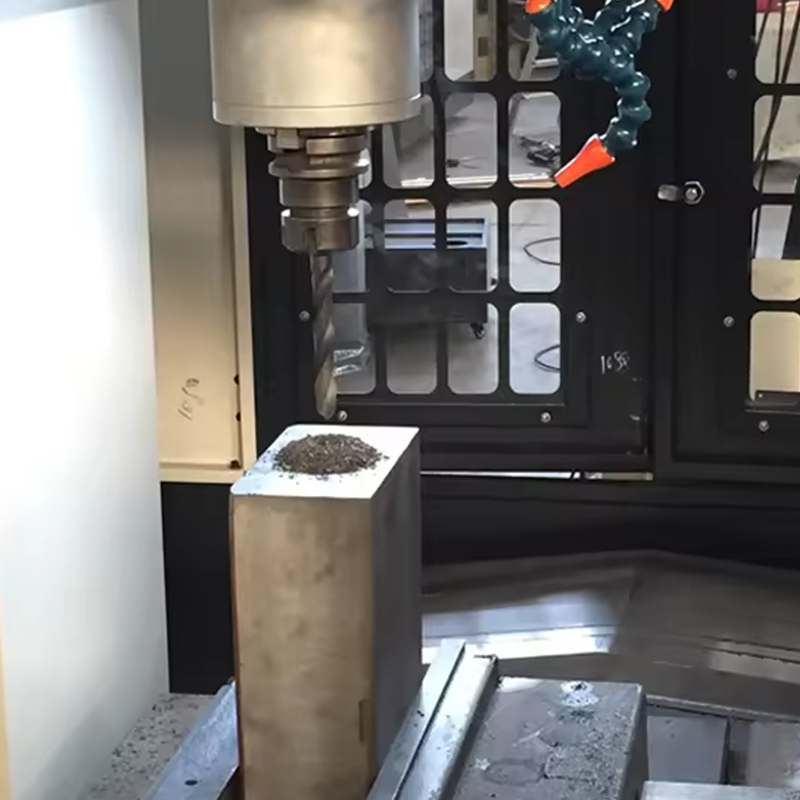
Surface finish is measured most commonly as Ra, the arithmetical mean roughness, expressed in micrometers or microinches. The as-machined default coming straight off a mill is around Ra 3.2 micrometers, sometimes written as 125 microinches, and it includes visible tool marks. This is the cheapest finish available because nothing beyond a normal finishing pass is done to reach it, and it is entirely appropriate for non-critical faces, brackets, jigs, and fixtures, or anything that will be painted or coated afterward.
Moving to Ra 1.6 micrometers, sometimes called 63 microinches, is a solid general-purpose finish suitable for mating faces that do not seal, light-duty bearing seats with a press fit, and visible surfaces where appearance matters without requiring a mirror look. Most CNC shops hold this with a controlled finishing pass rather than a separate operation, adding roughly 10 to 20 percent cycle time on the affected features.
Below that, Ra 0.8 micrometers demands optimized cutting parameters, sharp tooling, and a stable, low-vibration setup, and it is the level typically specified for sealing faces, sliding interfaces, and precision bores. Going from Ra 3.2 to Ra 0.8 can increase machining cost on that feature by roughly 200 to 400 percent due to additional finishing passes and slower, more careful cutting parameters. Below roughly Ra 0.4 micrometers, milling and turning alone rarely hold the finish reliably across a full surface, and a secondary operation such as grinding, honing, lapping, or polishing typically does the final work.
| Material Family | Typical As-Machined Ra Range | Polished Ra Range |
|---|---|---|
| Aluminum alloys | 0.8 to 3.2 µm | 0.2 to 0.8 µm |
| Steel and stainless steel | 0.4 to 1.6 µm | 0.1 to 0.4 µm |
| Copper and copper alloys | 0.4 to 3.2 µm | 0.2 to 0.6 µm |
| Cast iron | 1.6 to 6.3 µm | Rarely polished |
How Surface Finish Is Actually Measured
Contact profilometers remain the most common measurement method, dragging a fine stylus across the surface to record vertical deviations and compute Ra directly. Optical measurement, using laser or white-light interferometry, captures a full surface profile without touching the part, which matters on soft or delicate materials that a stylus could mark. Some production floors still rely on a simple comparison method, holding the workpiece next to a set of reference plates for a fast pass or fail check, though this is only appropriate for looser finish callouts rather than tight ones tied to sealing or bearing performance.
How a CNC Gantry Milling Machine Holds Precision on Large Workpieces
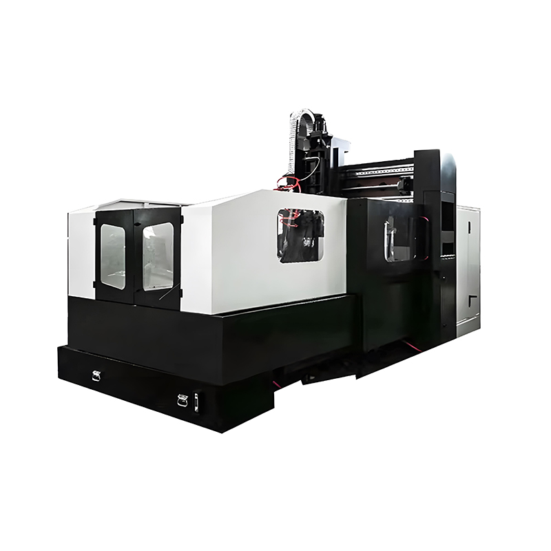
Once a part grows beyond what a standard vertical machining center's table can hold, a CNC Gantry Milling Machine becomes the practical answer. Instead of a single column supporting the spindle, a gantry design uses two vertical columns joined by a horizontal crossbeam that spans the entire worktable, letting the cutting head travel over workpieces measured in meters rather than centimeters. This bridge-like structure is what gives gantry machines their name, and it is also what allows them to keep cutting forces balanced symmetrically across the table instead of cantilevered off one side.
Structural Features That Keep Large Parts Accurate
Rigidity is everything on a gantry platform, because a workpiece that spans several meters will flex, vibrate, or drift out of tolerance if the frame is not built to resist it. Common design elements include box-type crossbeams with internal ribbing to resist bending, cast iron or HT300 column castings, and roller-type linear guideways rather than plain sliding ways. Some designs use a rotating-nut lead screw arrangement instead of a fixed nut, which spreads wear more evenly across the screw and reduces backlash over long travel distances. A staged propping system on the upper guideway, sometimes using multiple roller-type sliders, can extend the effective travel range of the moving slide to well over half the total guideway length while keeping static rigidity and dynamic accuracy consistent.
- Table sizes on large gantry mills commonly range from around 3 by 1.5 meters up to 6 by 2.5 meters or larger for shipbuilding and energy sector parts
- Spindle interfaces such as BT40, BT50, or larger tapers are matched to torque requirements for heavy stock removal
- Three, four, and five-axis gantry configurations exist, with five-axis versions used for contoured aerospace and mold surfaces
- Control systems from major CNC brands handle the coordinate geometry needed for multi-axis toolpaths across large travel ranges
- Chip removal slots and a box-type base wall strengthen static rigidity and dynamic accuracy of the machine base itself
| Specification | Typical Range |
|---|---|
| Worktable size | 3m x 1.5m up to 6m x 2.5m or larger |
| Axis configuration | 3-axis, 4-axis, or 5-axis |
| Guideway type | Roller-type linear guides, box-type crossbeam |
| Spindle taper | BT40, BT50, or larger for heavy stock removal |
| Typical applications | Large molds, aerospace structures, shipbuilding parts, energy components, heavy machinery frames |
Five-Axis Gantry Configurations for Complex Surfaces
Where a large part also carries complex contoured geometry rather than simple flat faces, a five-axis gantry configuration adds two rotational axes to the standard three linear axes, giving the cutting tool full access to angled and curved surfaces without repositioning the workpiece. This matters for large molds, turbine housings, and aerospace structural panels, where flipping or re-clamping a multi-ton workpiece to reach a different face is both slow and a fresh source of positional error. Eliminating that re-setup is often the single biggest precision advantage a five-axis gantry machine offers over a simpler three-axis configuration on the same part.
The tradeoff is footprint and investment: a large-format gantry milling machine occupies significant floor space and represents a substantial capital purchase for a shop, with fully equipped machines commonly priced from around 200,000 dollars up to well over 1,000,000 dollars depending on table size, axis count, and spindle power. This is why they are usually reserved for parts that genuinely cannot be produced any other way rather than general job-shop work.
Material Behavior Under the Cutting Tool
Tolerance is not only a machine question, it is a materials question. Every cutting tool deflects slightly under load, and that deflection eats directly into the tolerance budget. A standard end mill cutting aluminum such as 6061-T6 typically deflects somewhere between 0.0005 and 0.002 inches, depending on tool stick-out length, diameter, and how aggressively it is cutting. At a standard tolerance of plus or minus 0.005 inches, that deflection sits comfortably inside the allowed window. At plus or minus 0.001 inches, the same deflection can consume the entire tolerance band on its own.
Common Adjustments for Harder-to-Hold Materials
- Shorter, stiffer tooling to minimize deflection on finish passes
- Reduced feed rate and depth of cut on the final pass rather than the roughing pass
- A spring pass, meaning a final pass at zero additional depth that lets the tool recover from deflection and clean the surface
- Temperature-stable shop conditions, since thermal expansion in steel and aluminum both shift dimensions measurably across a working day
- Climb milling rather than conventional milling on finishing passes, since cutting with the direction of feed generally produces a better surface and extends tool life
Stainless steels and tool steels generally hold tight tolerance more predictably than aluminum because they deflect less, but they cut slower and wear tooling faster, which shifts the cost tradeoff in a different direction. Round features such as shafts and bores are usually easier to hold tightly on a lathe than on a mill, since the rotating part provides a naturally stable reference axis that a multi-axis milling toolpath does not have.
Coolant strategy also plays a direct role in dimensional stability. High-pressure flood coolant does more than lower cutting temperature; it clears chips away from the cutting zone before they can be re-cut and mar the surface, and it lubricates the cutting edge to reduce friction and prevent material from welding onto the tool tip. A shop running dry or under-cooled on a tight-tolerance job is very often trading dimensional consistency for a small cycle time saving that is not worth it.
Workholding and Fixturing for Repeatable Precision
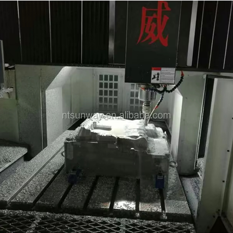
Vibration, sometimes called chatter, is one of the most common enemies of both tolerance and surface finish, and it almost always traces back to insufficient rigidity somewhere in the system rather than the cutting tool itself. A well-maintained machine, a securely clamped workpiece, and the shortest, most rigid tooling that reaches the feature together form the rigidity chain that keeps a cut stable from the first pass to the last.
Fixture design becomes especially important once a part requires multiple setups to reach every feature. Each additional setup introduces a fresh source of positional error, since the part must be re-located relative to the machine's coordinate system every time it is unclamped and reclamped. Reducing the number of setups, either through a five-axis machine that reaches more of the part in one clamping or through a dedicated fixture built for the specific job, is one of the most reliable ways to hold tight tolerance across features that must relate accurately to one another.
- Dedicated fixtures reduce setup time and improve repeatability across a production run
- Vises and modular clamping work well for simple prismatic shapes with generous clamping surfaces
- Vacuum fixturing suits thin, delicate, or large flat panels where mechanical clamping would distort the part
- Custom tooling plates on large gantry machines locate oversized or irregular parts consistently across multiple operations
Why Tighter Tolerance and Finish Add Cycle Time, Not Just Cost
A common misunderstanding is that tolerance and surface finish are purely quality control line items. In reality, tighter numbers change the machining program itself. Moving a four-sided housing from plus or minus 0.005 inch to plus or minus 0.001 inch on all faces can increase total cycle time by 40 to 80 percent, because the finishing passes slow down, sometimes splitting one finishing pass into two or three lighter passes to keep tool deflection and heat generation under control.
This matters most on batch production, where cycle time differences compound across dozens or hundreds of parts. A part that only needs tight tolerance on one bore or one mating face is far cheaper to produce than a part where every dimension is called out at the tightest available grade, even though the raw material and machine time might look similar on paper. The same logic applies to surface finish callouts placed on an entire part rather than the handful of faces that actually need them.
Toolpath and Programming Considerations
The CAM programming stage is where a lot of the cycle time decision actually gets made, well before the part reaches the machine. Programmers choosing stepover distance, finishing strategy, and cutting direction are directly trading surface finish and tolerance against cycle time. A tighter stepover on a contoured surface produces a smoother finish but adds passes; a finishing strategy that follows the part's natural surface curvature rather than a simple raster pattern tends to reduce witness marks on complex geometry, which matters most on visible or sealing surfaces.
Verifying Precision After the Part Comes Off the Machine
Holding a tolerance on the machine is only half the job; confirming it afterward is the other half. Coordinate measuring machines remain the standard tool for checking complex geometric features, while simpler dimensional checks can be done with calipers, micrometers, and height gauges for less demanding tolerance grades. For statistically controlled production runs, shops track process capability, often shortened to Cpk, where a value at or above 1.67 indicates a process that consistently keeps parts well within the specified tolerance rather than drifting toward the edges of the allowed range.
Surface finish verification uses a parallel set of tools. A contact profilometer with a stylus remains the most common instrument for a direct Ra reading, while optical systems using laser or white-light interferometry capture a full surface profile without touching the part, which is useful on soft or delicate materials. Comparison against reference plates is faster but only appropriate for looser finish callouts rather than sealing or bearing surfaces where the exact value matters.
For large parts coming off a gantry milling machine, laser tracking and portable arm-based measurement systems are increasingly used because the part itself is often too large to move onto a fixed coordinate measuring machine table, so the measurement equipment comes to the part instead.
How Different Industries Apply These Tolerances
Aerospace Structures and Components
Aerospace work sits at the tight-tolerance and ultra-precision end of the scale for flight-critical features, combined with a demand for repeatable surface finish on sealing and mating faces. Large structural panels and mold tooling used to form composite or metal aircraft parts are frequently produced on five-axis gantry machines specifically because the panel geometry is both large and contoured, and repositioning a multi-meter panel between operations would introduce unacceptable error.
Medical Devices and Implants
Medical implants and surgical instrument components often call for ultra-precision tolerance alongside very fine surface finish, since both dimensional accuracy and a smooth, bio-compatible surface texture directly affect how the part performs in the body. These parts are typically small compared to aerospace structures, so they are usually produced on high-precision vertical or multi-axis machining centers rather than gantry equipment, but the tolerance and finish discipline mirrors the tightest end of the charts covered earlier in this guide.
Mold Tooling and Die Making
Mold bases and cavity inserts demand both tight positional tolerance between mating halves and a fine surface finish on the cavity itself, since any roughness on the mold surface transfers directly onto every part molded from it. Large mold tooling is a core application for gantry-style milling, since a single mold base can span more than a meter across while still needing micron-level positional accuracy between its features.
Shipbuilding, Energy, and Heavy Machinery
Shipbuilding parts, energy sector components such as turbine housings, and heavy machinery frames represent the largest physical scale covered in this guide, frequently exceeding what any machine other than a large gantry mill could process in one setup. Tolerance requirements on these parts are usually closer to precision grade than ultra-precision grade, but the sheer size of the workpiece makes rigidity and thermal stability across the full travel range the dominant engineering challenge rather than micron-level tool deflection.
Cost Factors Buyers Should Actually Weigh
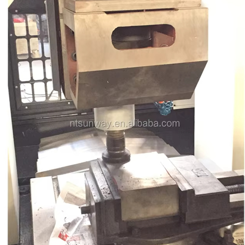
Tolerance and surface finish are the two biggest cost drivers in most precision milling quotes, but they are not the only ones. The following factors tend to move a quote up or down independently of the specified grade:
- Number of setups required, since each re-fixturing adds time and introduces a fresh source of positional error
- Batch size, which spreads programming and fixturing cost across more parts
- Material hardness and machinability, which changes tool wear rates and cutting speed
- Geometric complexity, including deep pockets, thin walls, and undercuts that limit tool access
- Inspection requirements, since full coordinate measuring machine reports on every dimension take considerably longer than spot-checking a handful of critical features
- Workpiece size relative to available machine capacity, since anything requiring a gantry-scale machine narrows the pool of shops that can even quote the job
Buyers who separate their drawing into critical and non-critical dimensions and finishes, rather than applying one tolerance and one Ra value across the whole part, consistently get more competitive quotes because the shop is not pricing every feature as if it were the tightest one on the page.
Matching the Process to the Part Instead of the Other Way Around
The most reliable approach to specifying a precision milling project starts with function, not with picking a tolerance grade first and designing around it. Mating surfaces, press fits, bearing seats, and sealing interfaces are the features that genuinely need tight tolerance and fine surface finish. Everything else on the part can typically sit at standard grade without affecting how the assembly performs.
For cylindrical features such as shafts, bores, and threads, turning on a lathe is usually the more cost-effective route to a tight tolerance than trying to hold the same number on a milling center, since the part rotates around a stable axis rather than relying on multi-axis tool movement. For prismatic parts, complex 3D surfaces, or anything requiring a large gantry-style setup because of sheer physical size, milling remains the practical choice, with the tolerance grade and surface finish selected feature by feature rather than applied uniformly.
When in doubt about whether a callout is achievable, cost-effective, or even necessary, a direct conversation with the machinist or programmer before finalizing the drawing consistently prevents both underspecified parts that fail in service and overspecified parts that cost far more than they need to.
Frequently Asked Questions
What is considered a standard tolerance for CNC milling?
Most shops default to roughly plus or minus 0.125 millimeters, or 0.005 inches, based on ISO 2768 medium grade, unless the drawing specifies something tighter.
How tight can a CNC gantry milling machine actually hold tolerance on a large part?
Well-built gantry machines with rigid box-type crossbeams and roller-type linear guides can hold precision-grade tolerance, often in the range of plus or minus 0.025 to 0.05 millimeters, even across multi-meter travel distances, though the exact figure depends heavily on fixturing and thermal stability in the shop.
Is milling or turning better for holding tight tolerance?
For round, rotational features like shafts and bores, turning is generally more cost-effective at holding tight tolerance because the part rotates around a fixed axis. Milling is the better choice for flat surfaces, pockets, and complex 3D geometry, or for parts too large to fit a lathe.
Why does tightening tolerance increase the price so much?
Tighter tolerance usually means slower finishing passes, sometimes split into multiple light passes instead of one, plus shorter and stiffer tooling and more thorough inspection afterward. All of that adds machine time and labor, not just material cost.
Do all dimensions on a part need the same tolerance grade?
No. The most cost-efficient approach applies tight tolerance only to functionally critical features, such as bearing seats or sealing surfaces, and leaves the rest of the part at standard grade.
What Ra value should a typical precision part target?
For most commercial precision parts, Ra 1.6 to 3.2 micrometers balances cost and function well. Sealing faces and precision bores often step down to Ra 0.8 micrometers, while anything finer usually requires a secondary grinding, honing, or polishing operation.
What materials are easiest to hold tight tolerance on?
Harder materials such as stainless steel and tool steel tend to deflect less under the cutting tool and hold tight tolerance more predictably than softer aluminum alloys, though they cut slower and wear tooling faster in exchange.
How does workholding affect precision on large parts?
Insufficient clamping or an unstable fixture is one of the most common causes of vibration and dimensional drift, especially on large or thin workpieces. Custom tooling plates and dedicated fixtures reduce setup count and keep repeat features positioned consistently relative to one another.
Why do five-axis gantry machines matter for large contoured parts?
A five-axis gantry configuration reaches angled and curved surfaces without re-clamping the workpiece, which matters most on large molds and aerospace panels where flipping a multi-ton part between operations would introduce positional error that is difficult to recover from later.
How is precision verified after machining is complete?
Coordinate measuring machines are the standard for complex geometric checks, while calipers, micrometers, and height gauges cover simpler dimensional checks. Large parts off a gantry machine are often measured with portable laser tracking or arm-based systems instead of a fixed table, and surface finish is separately checked with a profilometer or optical system.
PREV:What Is a CNC Milling Machine? Types, Uses & Gantry Guide
NEXT:What Does CNC Stand For? Understanding CNC Equipment
NEXT:What Does CNC Stand For? Understanding CNC Equipment
Interested in cooperation or have questions?
News
-
-
An EDM machine, also called an electrical discharge machining machine, uses controlled sparks to erode electrically conductive metal without direct contact between the tool and the workpiece. The workpiece is submerged in a diele...
READ MORE -
Cutting Tools Are Used to Convert Raw Material into Functional Parts Cutting tools are the hardened, wear-resistant elements that shear away unwanted material from a workpiece to create a finished component. They are applied in e...
READ MORE -
A CNC machine can cut, drill, mill, turn, burn, and shape almost any conductive or composite material with an accuracy that manual machines rarely match. The real question is not what a CNC machine can do in theory, but what a sp...
READ MORE
Related Products

-
Factory Address
Zhaxi Township Industrial Park, Nantong City, Jiangsu Province, China (west of Huaneng Power Plant)
-
Phone
+86-13615235768
+86-15950816906
-
Fax
+86-513-85632766
-
Email
pan.director@sunwayer.com
Stay Connected
lf you can't find the answer you're looking for, chat with our friendly team.
Stay Connected
Copyright © Nantong Sunway Science and Technology Development Co., Ltd. All Rights Reserved.
China CNC Equipment Manufacturers
Custom CNC Equipment Factory
