


 русский
 Español
A clearance fit is an assembly condition in which the minimum hole diameter is always larger than the maximum shaft diameter. In one sentence: the two mating parts are separated by a guaranteed positive gap, so they can slide, ro...
READ MORE
What Is a Clearance Fit? Learn Types, Tolerances, and CNC Machining Guide
Content
- 1 The Main Types of Clearance Fits
- 2 How the ISO 286 System Defines a Clearance Fit
- 3 How CNC Machining Produces a Clearance Fit That Actually Works
- 4 How to Measure and Verify a Clearance Fit on the Shop Floor
- 5 Where Clearance Fits Matter Most: Molds, Dies, and Precision Tooling
- 6 Six Common Mistakes When Specifying and Machining Clearance Fits
- 7 Frequently Asked Questions about Clearance Fits
- 7.1 What is the difference between a clearance fit, an interference fit, and a transition fit?
- 7.2 What does H7/g6 mean?
- 7.3 Is a clearance fit suitable for bearing assemblies?
- 7.4 Can a CNC machining center hold an H7/g6 clearance fit directly?
- 7.5 Why is the hole-basis system used for most clearance fits?
- 7.6 What is the smallest clearance that should be used for a sliding fit?
- 8 The Bottom Line
A clearance fit is an assembly condition in which the minimum hole diameter is always larger than the maximum shaft diameter. In one sentence: the two mating parts are separated by a guaranteed positive gap, so they can slide, rotate, or be fitted together by hand without pressing force. Take a 25 mm guide bore with an H7 tolerance (0 to +0.021 mm) and a g6 shaft (−0.007 to −0.020 mm). The worst-case clearance is never negative; it always falls between 0.007 mm and 0.041 mm.
Clearance fits are the opposite of interference fits, where the shaft is deliberately oversized and the parts are pressed or shrunk together. They are also different from transition fits, where a small overlap or a small gap can occur depending on the actual manufactured dimensions. A clearance fit is specified when the designer needs guaranteed relative motion, easy assembly and disassembly, room for a lubricating film, or a safety margin against thermal expansion and misalignment.
The Main Types of Clearance Fits
Not all clearance fits are the same. The amount of guaranteed gap determines whether a joint is a loose running fit or a tight sliding fit. In the ISO hole-basis system, the letter and number combination tells you exactly how much clearance to expect. The table below summarizes the five clearance fits most often quoted in machine tool drawings and mold specifications.
| Fit Type | ISO Designation | Typical Clearance (30–50 mm) | Primary Application |
|---|---|---|---|
| Loose running fit | H11/c11 | 0.12 – 0.36 mm | Agricultural machinery, long shafts, parts with poor alignment |
| Free running fit | H9/d9 | 0.07 – 0.17 mm | Electric motors, gearboxes, plain bearings at moderate speeds |
| Easy running fit | H8/e8 | 0.04 – 0.09 mm | Machine tool spindles, pumps, conveyor rollers, low-speed journals |
| Sliding fit | H7/g6 | 0.007 – 0.041 mm | Linear guideways, gear shift forks, sliding valves, ejector pins |
| Locational clearance fit | H7/h6 | 0 – 0.025 mm | Dowel pins, locating rings, parts that must be exactly positioned |
When you go from H11/c11 down to H7/g6, both the maximum and the minimum clearance shrink. That shrinking gap is exactly what converts a loose, forgiving fit into a precise sliding fit. The tighter the clearance, the more demanding the machining process must be.
How the ISO 286 System Defines a Clearance Fit
The notation H7/g6 contains every piece of information needed to define a clearance fit. The uppercase letter and number before the slash describe the hole; the lowercase letter and number after the slash describe the shaft. The letter is the fundamental deviation, which positions the tolerance zone relative to the nominal size. The number is the IT grade, which sets how wide that tolerance zone is.
In the hole-basis system, the hole is always an H zone, meaning its lower deviation is zero. The shaft letter is then chosen to create the desired type and size of clearance. A shaft with an "h" zone gives the smallest positive clearance; "g", "f", "e", "d", and "c" progressively increase the gap. For example, H7/g6 means an IT7 hole mated with an IT6 shaft whose fundamental deviation is "g".
The IT grade determines which machining process is realistic. The table below compares common IT grades for a 30–50 mm nominal dimension. These numbers are taken from the standard ISO 286 fundamental tolerance tables.
| IT Grade | Total Tolerance (µm) | Typical Machining Process | Used In |
|---|---|---|---|
| IT5 | 11 µm | Precision grinding, jig boring | Gauge components, bearing spindles |
| IT6 | 16 µm | Fine grinding, precise reaming | Sliding fit shafts (g6, f6) |
| IT7 | 25 µm | Reaming, precision CNC boring | Standard matched holes (H7) |
| IT8 | 39 µm | CNC milling, turning | General machined components |
| IT9 | 62 µm | Standard turning, milling | Loose running fits (H9/d9) |
| IT10 – IT11 | 100 – 160 µm | Rough machining, drilling | Very loose clearance fits (H11/c11) |
A 25 mm H7/g6 clearance fit works out like this: the H7 hole measures between 25.000 mm and 25.021 mm, while the g6 shaft measures between 24.993 mm and 24.980 mm. The minimum clearance is 25.000 minus 24.993, which is 0.007 mm. The maximum clearance is 25.021 minus 24.980, which is 0.041 mm. Both numbers are positive, so every part from the batch will assemble with a visible gap.
How CNC Machining Produces a Clearance Fit That Actually Works
A clearance fit is not created on the drawing board; it is created by the machine tool. The drawing only defines the limits. Whether the actual bore and shaft land inside those limits depends on spindle runout, ball screw accuracy, thermal growth, tool deflection, and machine rigidity. A well-built three-axis CNC vertical machining center can hold an IT7 tolerance on bored holes and an IT6 tolerance on ground shafts, which is exactly what H7/g6 and H7/f7 sliding fits require.
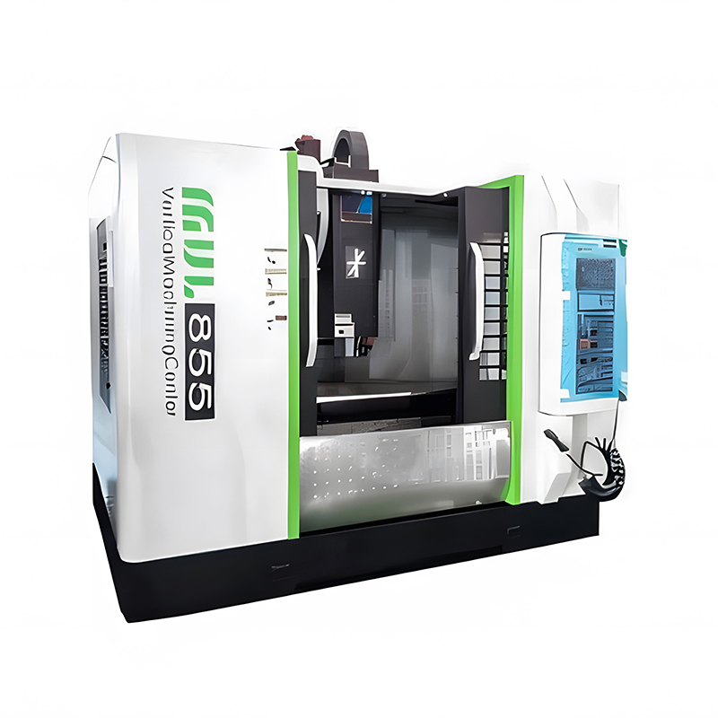
Take Sunway's VMC850L high-speed vertical machining center as a reference. Its cast iron structure, precision ground ball screws, and high-speed spindle give the stiffness needed to finish a 25 µm IT7 bore repeatedly. For a three-shift shop producing guide bushes, ejector pin holes, or bearing housings, the practical approach is to bore the hole first, measure it on the machine with a precision boring head, and then machine the shaft to the measured value. This "match machining" method narrows the effective clearance far below the full tolerance band.
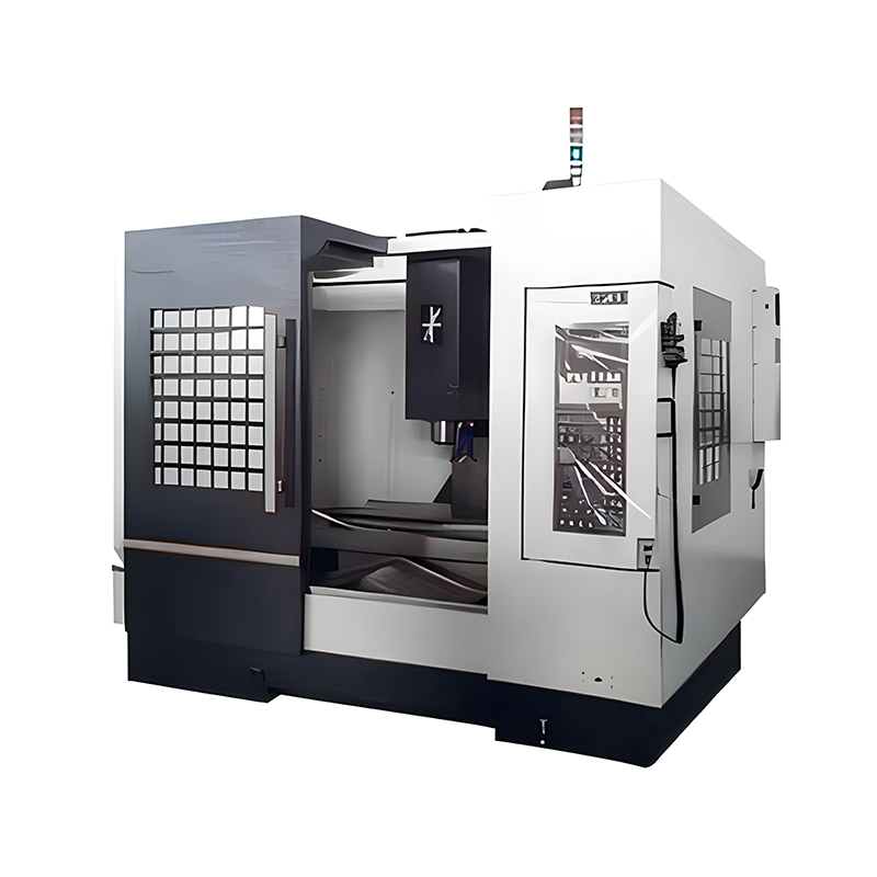 VMC850L Vertical Machining Center for Precision BoringIdeal for three-shift shops producing guide bushes, ejector pin holes, or bearing housings, this machine enables match machining to tighten effective clearance beyond the full tolerance band.View Product →
For large structural parts that cannot fit on a vertical machining center table, the same logic applies on a gantry machine. The extended bridge structure and heavy crossbeam keep the spindle stable over long strokes, which is critical when boring deep holes that must remain straight and cylindrical. If you are machining large frames or die plates with clearance-fit bores, you will find useful process detail in this comprehensive guide to CNC gantry milling machines.
Thermal management is the part most shops underestimate. The ISO 286 standard assumes a reference temperature of 20 °C. A machine running for several hours without temperature control can shift a bore by more than the entire IT7 tolerance band. Cutting fluid temperature, ambient shop temperature, and even the heat from your hand holding a micrometer all matter when the final clearance is only 0.007 mm.
How to Measure and Verify a Clearance Fit on the Shop Floor
The only way to know you have a true clearance fit is to measure the real parts at the reference temperature of 20 °C. A clearance fit can look perfect on a gauge but fail in assembly if the measurement method, surface roughness, or temperature is ignored. This is why machine shops combine direct measurement with functional go/no-go checks.
- Measure the bore at three depths and in two perpendicular directions using a three-point internal micrometer or a bore gauge. Record every reading, not just the average.
- Measure the shaft at the same relative positions with an external micrometer. Look for taper and lobing, which are common when grinding between centers.
- Calculate the actual clearance range: minimum clearance equals minimum hole diameter minus maximum shaft diameter; maximum clearance equals maximum hole diameter minus minimum shaft diameter.
- Check surface roughness with a profilometer. For sliding fits, a roughness of 0.8 to 1.6 µm Ra is typical; rougher surfaces reduce the effective clearance even when diameters are correct.
- Perform a trial assembly on a sample part. The shaft should advance smoothly under light hand force and, for sliding fits, move without audible stick-slip.
For large housings and structural components, a precision gantry machine is often used both to machine the datum surfaces and to hold the tight cylindrical tolerance needed for subsequent measurement on a coordinate measuring machine. Sunway's LM1613 high-precision metal milling gantry CNC machine is built for exactly this type of large-part work, where the bore position tolerance and the bore diameter tolerance must both be respected.
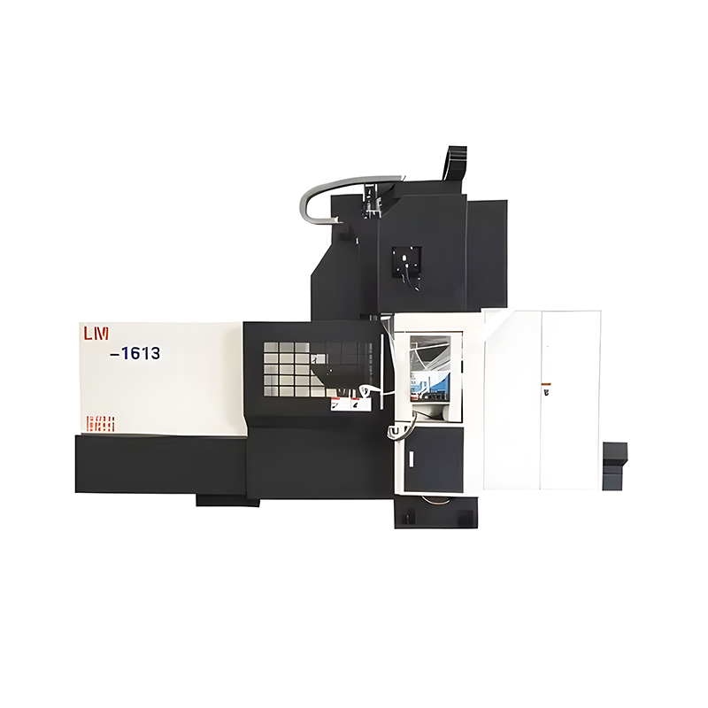 LM-1613 Gantry CNC Machine for Large Structural PartsBuilt for large housings and structural components, its 22kW spindle and 0.008mm positioning accuracy ensure both bore position and diameter tolerances are held for subsequent CMM inspection.View Product →
When production volume justifies it, dedicated plug gauges for the hole and snap gauges for the shaft give the fastest go/no-go verification. A plug gauge built to the minimum hole diameter will enter every acceptable bore; a snap gauge set to the maximum shaft diameter will reject any shaft that is too large. That simple pair of gauges prevents a bad batch from ever reaching assembly.
Where Clearance Fits Matter Most: Molds, Dies, and Precision Tooling
In mold and die manufacturing, a clearance fit is not a luxury; it is a functional requirement that decides whether a mold opens, guides, and ejects correctly. Three applications dominate the shop floor.
Guide Pillars and Guide Bushes
The guide pillar-bush pair in a mold uses a sliding fit such as H7/g6 or a slightly looser H7/f7. The pillar must enter the bush cleanly over the full stroke, even when the mold is hot and the plates have grown thermally. A transition fit would cause galling; an interference fit would make the mold impossible to open. The positive clearance also retains a thin oil film that prevents metal-to-metal contact during high-speed cycling.
Ejector Pins and Sleeves
Ejector pins move in and out of the mold cavity on every cycle. A clearance fit with a controlled gap of roughly 0.008 to 0.025 mm lets the pin slide freely while still supporting the molded part without flash. If the clearance is too small, the pin sticks; if it is too large, plastic material burrs into the gap and the pin seizes after a few thousand cycles.
Die Plates and Punch Assemblies
Stamping dies rely on a precisely controlled clearance between the punch and the die plate. Although this is sometimes called a "cutting clearance," it is fundamentally a clearance fit between two hardened steel components. The gap controls the quality of the sheared edge and directly affects tool wear. Wire-cut EDM is the standard process for producing these highly accurate openings because it creates a smooth, straight wall with a tolerance that supports clearance fits down to a few micrometres. For example, Sunway's DZ653 high-precision moving-column wire-cutting machine holds the kind of positional and dimensional accuracy that die makers depend on for punch-die clearance.
 DZ-653 Wire Cutting Machine for Punch-Die ClearanceEngineered for stamping dies requiring controlled punch-die clearance, its moving-column design minimizes thermal deformation and delivers sub-micron precision for long-running clearance fits.View Product →
The common thread in all these applications is that the clearance fit must survive real operating conditions: temperature, wear, lubrication, and repeated cycles. Choosing the right nominal fit is only half the job; the other half is machining it with equipment stiff enough to hold the tolerance on every production piece.
Six Common Mistakes When Specifying and Machining Clearance Fits
Most clearance fit failures are not caused by the design standard; they are caused by misunderstanding the practical conditions around the fit. Here are the six mistakes that appear most often in CNC machine shops and mold workshops.
- Mistake 1 – Choosing a sliding fit where a locational fit is needed. A sliding fit such as H7/g6 has a measurable minimum clearance. If the part is supposed to stay stationary once positioned, use a locational clearance fit H7/h6 instead. The near-zero clearance keeps the part centered and rigid.
- Mistake 2 – Forgetting the effect of surface roughness. Two parts with identical diameters but different surface finishes will not feel the same in assembly. A 3.2 µm Ra shaft peaks into the 1.6 µm Ra bore, effectively reducing the clearance and increasing friction. Always specify surface finish together with the fit.
- Mistake 3 – Ignoring thermal expansion. A shaft made of steel and a housing made of aluminum expand at very different rates. A fit that slides smoothly at 20 °C can become an interference fit at 80 °C. Calculate the expected temperature range before finalizing the fit class.
- Mistake 4 – Mixing hole-basis and shaft-basis systems. If one drawing uses H7/g6 and another uses G7/h6, the shop must treat them as completely different fits. Mixing them in a single assembly leads to unintended clearance values and rejected batches.
- Mistake 5 – Overspecifying the tolerance. Tightening an IT8 fit to IT5 doubles the machining and measurement cost while offering little functional benefit in most applications. A 10 µm gain in accuracy can easily multiply the rejected part rate on a standard CNC machine.
- Mistake 6 – Trusting a worn tool or an unstable machine setup. Spindle runout, bent drawbar, worn guideways, and thermal drift all push the finished hole out of the tolerance band. A routine check of spindle runout against a certified test bar is the fastest way to protect a clearance fit.
Frequently Asked Questions about Clearance Fits
What is the difference between a clearance fit, an interference fit, and a transition fit?
In a clearance fit, the hole is always larger than the shaft, so the assembly always has a positive gap. In an interference fit, the shaft is always larger than the hole, so the assembly requires pressing or heating. In a transition fit, the actual dimensions can produce either a small gap or a small overlap, which means the assembly is uncertain in terms of clearance and is used for precise centering rather than for motion.
What does H7/g6 mean?
H7/g6 is the most common sliding clearance fit in the ISO 286 system. The H7 hole has an IT grade 7 tolerance with the lower deviation at zero, and the g6 shaft has an IT grade 6 tolerance positioned slightly below the nominal size. For a 25 mm diameter, the hole is 25.000 to 25.021 mm and the shaft is 24.993 to 24.980 mm, giving a clearance between 0.007 mm and 0.041 mm.
Is a clearance fit suitable for bearing assemblies?
For most bearing applications, the correct fit depends on which ring rotates. A rotating bearing inner ring normally uses a transition or light interference fit on the shaft to prevent creep, while the stationary outer ring often uses a clearance fit in the housing. The classic clearance fits used with bearings are H7/h6, H7/js6, and H7/g6, depending on the load and speed conditions.
Can a CNC machining center hold an H7/g6 clearance fit directly?
Yes. A rigid three-axis CNC vertical machining center with a precision boring head or a reamer can hold the 21 µm IT7 hole tolerance on a 25 mm bore in normal production conditions. The shaft side should be finish ground to hold the 13 µm IT6 tolerance. Match machining, where the shaft is ground after the hole is measured, can reduce the effective clearance variation to a few micrometres.
Why is the hole-basis system used for most clearance fits?
In hole-basis fits, the hole keeps an H tolerance with a zero lower deviation, and different shaft grades create all the fit variations. This is more economical because a single standard reamer or boring bar produces the hole, while the shaft can be ground to different sizes on the same grinder. Shaft-basis fits are reserved for applications where the shaft is already a standard purchased component, such as a ground shaft or a bearing journal.
What is the smallest clearance that should be used for a sliding fit?
For fine mechanical assemblies, a minimum clearance of 0.005 to 0.010 mm is generally considered the practical lower limit for a lubricated sliding fit. Below that range, the oil film cannot form reliably, surface peaks begin to contact, and the assembly becomes sensitive to temperature changes. The H7/g6 fit, with a minimum clearance of 0.007 mm at 25 mm diameter, is widely accepted as the tightest reliable sliding fit for normal production.
The Bottom Line
A clearance fit is only as good as the machine that produces it and the measurement system that verifies it. Start by selecting the correct fit class from the ISO 286 system, then choose a machining process capable of holding the required IT grade, and finally confirm the actual clearance on sample parts at 20 °C. For shops working on molds, dies, bearing housings, and structural components, the combination of a stiff vertical machining center, a large gantry machine, and a precision wire EDM covers nearly every clearance fit scenario encountered in production.
If you are planning a new machining line or need to replace equipment that can no longer hold the tolerance your prints demand, contact Nantong Sunway's engineering team to discuss machine specifications, standard capabilities, and application-matched configurations.
PREV:No previous article
NEXT:What Is Heat Treatment? A Practical Guide for CNC Machining & Mold Makers
NEXT:What Is Heat Treatment? A Practical Guide for CNC Machining & Mold Makers
Interested in cooperation or have questions?
News
-
-
Heat treatment is a controlled thermal process that changes the mechanical properties of metal by heating it to a specific temperature, holding it there, and then cooling it at a rate chosen to produce a desired internal structur...
READ MORE -
An EDM machine, also called an electrical discharge machining machine, uses controlled sparks to erode electrically conductive metal without direct contact between the tool and the workpiece. The workpiece is submerged in a diele...
READ MORE -
Cutting Tools Are Used to Convert Raw Material into Functional Parts Cutting tools are the hardened, wear-resistant elements that shear away unwanted material from a workpiece to create a finished component. They are applied in e...
READ MORE
Related Products

-
Factory Address
Zhaxi Township Industrial Park, Nantong City, Jiangsu Province, China (west of Huaneng Power Plant)
-
Phone
+86-13615235768
+86-15950816906
-
Fax
+86-513-85632766
-
Email
pan.director@sunwayer.com
Stay Connected
lf you can't find the answer you're looking for, chat with our friendly team.
Stay Connected
Copyright © Nantong Sunway Science and Technology Development Co., Ltd. All Rights Reserved.
China CNC Equipment Manufacturers
Custom CNC Equipment Factory
