


 русский
 Español
Heat treatment is a controlled thermal process that changes the mechanical properties of metal by heating it to a specific temperature, holding it there, and then cooling it at a rate chosen to produce a desired internal structur...
READ MORE
What Is a CNC Milling Machine? Types, Uses & Gantry Guide
Content
- 1 What Is a CNC Milling Machine
- 2 From Manual Handwheels to Digital Control
- 3 How a CNC Milling Machine Actually Works
- 4 Common Milling Operations Performed on These Machines
- 5 Main Types of CNC Milling Machines
- 6 What Makes a CNC Gantry Milling Machine Different
- 7 Key Components of a CNC Milling Machine
- 8 Advantages of CNC Milling Over Manual Milling
- 9 Materials Commonly Machined on CNC Mills
- 10 Industries That Rely on CNC Milling Machines
- 11 Cost Factors to Consider Before Investing in CNC Milling Equipment
- 12 How to Choose the Right CNC Milling Machine
- 13 Maintenance Practices That Extend Machine Life
- 14 Current Trends in CNC Milling Technology
- 15 CNC Milling Compared With Other Manufacturing Processes
- 16 Frequently Asked Questions
- 16.1 What is the difference between a CNC milling machine and a CNC router
- 16.2 What size parts can a CNC Gantry Milling Machine handle
- 16.3 How accurate is CNC milling
- 16.4 Can one CNC milling machine cut multiple materials
- 16.5 Why do large parts require a gantry-style machine instead of a standard mill
- 16.6 How long does it take to program a new part for CNC milling
- 16.7 Do gantry milling machines require a special foundation
What Is a CNC Milling Machine
A CNC milling machine is a computer-controlled machine tool that removes material from a solid workpiece using rotating cutting tools to produce parts with precise dimensions, flat surfaces, slots, pockets, and complex three-dimensional shapes. The letters CNC stand for Computer Numerical Control, meaning the cutting path, spindle speed, feed rate, and tool changes are all directed by a digital program rather than by a machinist turning handwheels. Among the many configurations available, the CNC Gantry Milling Machine is built for large, heavy, or long workpieces such as ship components, machine bases, and wind turbine parts, using a bridge-style structure that spans over the table instead of a traditional column design.
In short: a CNC milling machine converts a digital drawing into a physical part by moving a rotating cutter along X, Y, and Z axes, and often additional rotary axes, according to programmed coordinates, achieving repeatable accuracy that manual milling cannot match. The remainder of this guide walks through how the machine works, the structural types available, how a gantry configuration differs from a column mill, the industries that depend on this equipment, and the practical factors that go into selecting, running, and maintaining one.
From Manual Handwheels to Digital Control
Milling as a metalworking process predates computers by more than a century, originally relying entirely on operators reading blueprints and turning graduated handwheels to move the table by fractions of a millimeter. The introduction of numerical control in the mid-twentieth century replaced those handwheels with punched tape and stepper motors, and later with fully digital servo control. This shift did more than speed up production; it decoupled part accuracy from an individual operator's hand-eye coordination and made it possible to reproduce the exact same cut thousands of times in a row.
Modern controllers extend this legacy with real-time feedback loops, thermal compensation that adjusts for spindle heat expansion, and networked monitoring that lets a shop floor manager track machine utilization from an office computer. None of this changes the underlying physics of cutting metal, but it does mean that a CNC milling machine purchased today behaves far more predictably across a full production shift than equipment built even a decade ago.
How a CNC Milling Machine Actually Works
The process starts with a CAD model, which is converted into machine-readable G-code through CAM software. This code tells the machine exactly where the cutting tool should travel, how fast the spindle should rotate, and how quickly the table or head should feed into the material. Once loaded, the controller executes the program automatically, and the machine repeats the same motion path for every part in the batch, which is why CNC milling is favored for both prototyping and volume production.
Core Motion System
Most machines use ball screws or linear motors paired with servo motors to achieve positioning accuracy that commonly falls between 0.005 mm and 0.02 mm on industrial-grade equipment. Linear guideways or box ways carry the moving axes, while a closed-loop feedback system continuously compares the actual position against the programmed position and corrects any deviation in real time.
- Spindle: rotates the cutting tool, typically at speeds from 6,000 to over 24,000 RPM depending on the material and tool diameter
- Tool changer: automatically swaps cutting tools during a program, with magazine capacities ranging from 12 to over 60 positions
- Controller: interprets G-code and coordinates every axis movement in real time
- Coolant system: removes heat and chips from the cutting zone to protect both the tool and the workpiece surface finish
- Chip management: augers or conveyors clear metal chips continuously so they do not re-cut into the finished surface
Reading a Basic G-Code Program
A typical program begins with setup lines that define the tool, spindle speed, and coordinate system, followed by movement commands such as rapid positioning and linear or circular interpolation. Programmers rarely write every line by hand for complex parts; CAM software generates the majority of the toolpath automatically based on the selected cutting strategy, and the programmer's job becomes verifying the simulation, selecting sensible feeds and speeds, and checking for tool or fixture collisions before the file is sent to the machine.
Common Milling Operations Performed on These Machines
A single CNC milling machine can perform many different cutting operations without changing the fundamental setup, simply by loading a different tool and toolpath. Understanding the main operation types helps explain why the process is so versatile compared to other manufacturing methods.
Face Milling
A wide-diameter cutter passes across the top surface of the workpiece to flatten it and establish a reference plane for subsequent operations. This is usually the first cut performed on a raw casting or bar stock.
Slot Milling and Pocketing
End mills cut channels, keyways, and enclosed pockets into the material. Pocketing typically involves multiple passes that step down in depth, clearing out material layer by layer until the final cavity shape and depth are reached.
Profile Milling and Contouring
The tool follows the outer or inner edge of a part shape, often used to cut a component free from surrounding stock or to finish a curved boundary to its final dimension.
Drilling, Boring, and Tapping
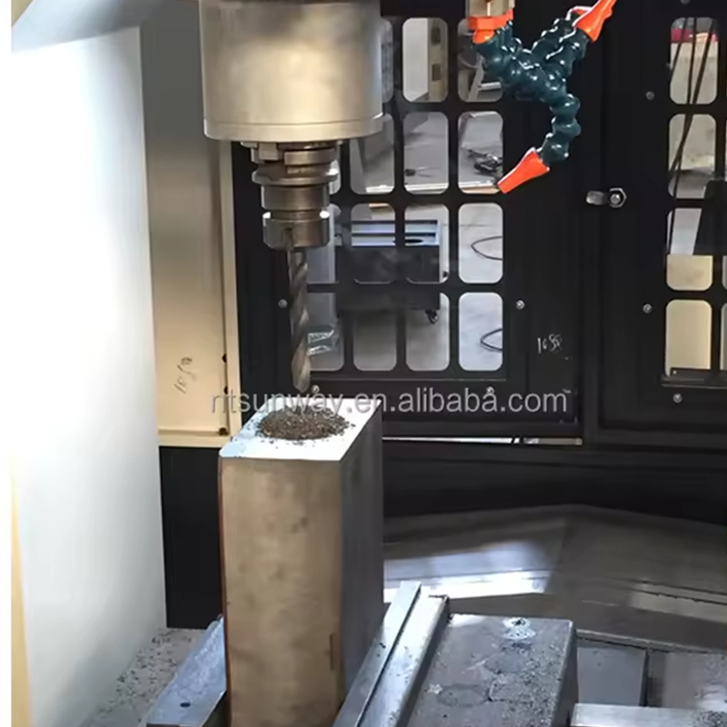
Because the spindle can hold different tool types in sequence, the same machine can drill holes, bore them to a precise diameter, and cut internal threads without moving the part to a separate machine, which reduces the number of setups and preserves positional accuracy between features.
Main Types of CNC Milling Machines
Not every milling machine is built the same way. The structural layout determines how large a part can be machined, how rigid the cut will be, and how much the machine will cost to install and run. The table below compares the most common configurations used in industrial workshops today.
| Machine Type | Typical Workpiece Size | Best For |
|---|---|---|
| Vertical Machining Center (VMC) | Small to medium | Molds, brackets, general parts |
| Horizontal Machining Center (HMC) | Medium | High-volume production, multi-face parts |
| CNC Gantry Milling Machine | Large to extra-large | Ship bases, machine tool beds, wind energy parts |
| Bed-Type Milling Machine | Medium to large | Heavy cutting, long workpieces |
| Turret Milling Machine (CNC-retrofit) | Small | Tool rooms, repair shops, light production |
Vertical and horizontal machining centers cover the majority of general manufacturing needs, but once a workpiece exceeds roughly one to two meters in a single dimension, or its weight climbs into the multi-ton range, a bed-type or gantry configuration becomes the more practical choice because the frame is designed from the ground up to resist deflection over a long span.
What Makes a CNC Gantry Milling Machine Different
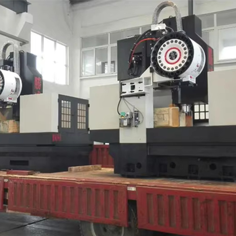
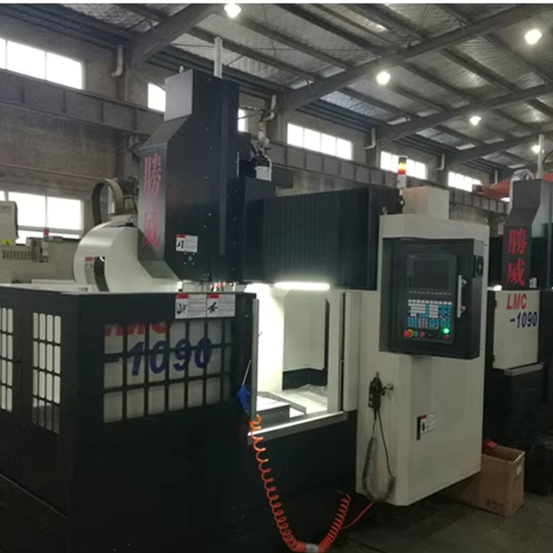
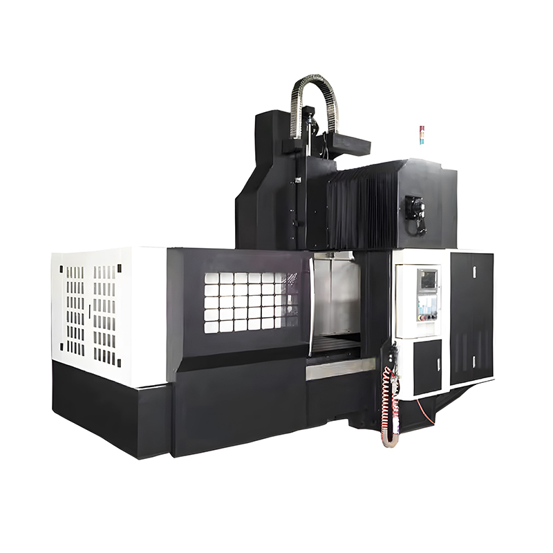
A CNC Gantry Milling Machine replaces the single-column structure of a standard mill with two vertical supports connected by a horizontal beam, forming a bridge that carries the spindle head across the workpiece. Because the load path runs through both sides of the frame instead of one column, the structure resists bending and vibration far better when cutting large or heavy parts, which is why gantry machines are the standard choice for workpieces measuring several meters in length or weighing several tons.
Moving-Gantry vs Fixed-Gantry Designs
In a moving-gantry design, the bridge itself travels along fixed rails set into the floor while the workpiece stays stationary, which is preferred for extremely long or heavy parts because the workpiece never needs to be repositioned once it is fixtured. In a fixed-gantry design, the bridge stays in place and the table moves beneath it, which can offer simpler foundation requirements but generally limits the maximum part length to the travel of the table.
Typical Applications
- Machining large machine tool beds and columns
- Milling ship engine bases and hull components
- Producing wind turbine hubs, flanges, and gearbox housings
- Milling large aluminum molds for the automotive and rail industries
- Machining structural steel components for heavy construction equipment
Multi-Head and Twin-Spindle Configurations
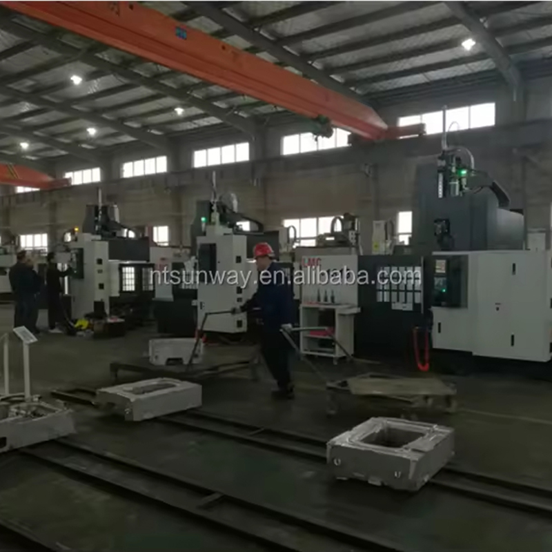
Because the bridge already spans the full width of the table, many gantry machines are built with two or more independent spindle heads mounted on the same crossbeam. This allows a shop to rough one section of a large casting while finishing another section simultaneously, which meaningfully shortens the cycle time on parts that would otherwise sit on the table for many hours in a single-head setup.
Key Components of a CNC Milling Machine
Understanding the main components helps explain why CNC mills can hold tight tolerances repeatedly across thousands of cycles.
Base and Frame
Cast iron or welded steel frames absorb cutting vibration and provide long-term dimensional stability. Heavier frames generally allow deeper cuts and higher metal removal rates without sacrificing accuracy. On large gantry machines, the base is often segmented into multiple bolted sections and installed on a reinforced concrete foundation to keep the full structure level over a long working life.
Spindle and Tooling
The spindle holds and rotates the cutting tool. Spindle taper types such as BT40, BT50, or HSK determine how much torque and tool weight the machine can handle, which is especially relevant for gantry mills cutting steel or cast iron at high metal removal rates. Tool materials range from high-speed steel for softer materials to carbide and coated carbide inserts for hardened steels and abrasive cast alloys.
Control System
Common industrial controllers include Fanuc, Siemens, and Mitsubishi systems, each offering programmable axis limits, tool life management, and diagnostic functions that reduce unplanned downtime. Newer controllers also support conversational programming interfaces that let operators build simple toolpaths directly at the machine without a separate CAM workstation.
Workholding and Fixtures
Vises, clamps, and custom fixtures hold the part securely during cutting. On large gantry machines, T-slot tables allow custom fixturing to be bolted directly to the table surface, since standard vises are rarely large enough to secure multi-ton castings or fabrications.
Advantages of CNC Milling Over Manual Milling
| Factor | Manual Milling | CNC Milling |
|---|---|---|
| Repeat accuracy | Depends on operator skill | Consistent within microns |
| Complex geometry | Difficult or impossible | Handled through programmed paths |
| Production speed | Slower, labor-intensive | Faster once programmed |
| Unattended operation | Not possible | Supported with automatic tool changers |
| Documentation and traceability | Minimal, relies on operator notes | Program files stored and reused for future runs |
Because the cutting path is fully programmed, CNC milling eliminates the human variability that naturally occurs in manual machining, which is one of the main reasons the process has become the default choice for parts that require close tolerances or complex three-dimensional surfaces. The same program file can also be archived and reused months or years later, giving a shop the ability to reproduce a part exactly without redesigning the toolpath from scratch.
Materials Commonly Machined on CNC Mills
CNC milling machines are not limited to a single material family, and the cutting parameters simply adjust to suit the workpiece.
- Aluminum alloys: fast to cut, widely used for prototypes, housings, and aerospace structural parts
- Carbon and alloy steels: common in machine bases, gears, and structural fabrications
- Stainless steel: used where corrosion resistance matters, such as food processing or marine equipment
- Cast iron: favored for machine tool beds and engine components due to its vibration-damping properties
- Engineering plastics: used for low-load brackets, jigs, and electrical insulating components
- Titanium alloys: chosen for aerospace parts requiring a high strength-to-weight ratio, though it requires slower feeds and specialized tooling
Industries That Rely on CNC Milling Machines
CNC milling appears across nearly every sector that manufactures metal or engineering plastic parts:
- Automotive manufacturing: engine blocks, transmission housings, and jigs
- Aerospace: structural brackets, turbine housings, and lightweight airframe parts
- Heavy equipment: gearbox housings, chassis components, hydraulic blocks
- Energy: wind turbine hubs and flanges, often produced on gantry-type mills due to their size
- Mold and die making: precision cavities for plastic injection and die casting
- Rail transportation: bogie frames, coupler housings, and large structural fabrications
- Shipbuilding: engine seatings, rudder components, and propulsion system housings
In sectors like shipbuilding and heavy equipment manufacturing, the parts involved are frequently too large for a standard vertical machining center, which is why gantry-style equipment has become closely associated with these industries specifically.
Cost Factors to Consider Before Investing in CNC Milling Equipment
The purchase price of a CNC milling machine is only one part of the total cost picture. Buyers typically also weigh the following factors before committing to a specific machine class.
Foundation and Installation
Large bed-type and gantry machines often require a reinforced concrete foundation designed specifically for the machine's weight distribution, which adds both cost and lead time compared to a standard vertical machining center that can typically sit on a normal shop floor.
Tooling and Consumables
Cutting tools, coolant, and fixture components represent an ongoing operating cost. Harder materials and larger cutting depths both increase tool wear rates, so the expected material mix should factor into the tooling budget from the outset.
Power and Floor Space Requirements
Spindle motors, coolant pumps, and auxiliary hydraulics on large machines draw significantly more power than a benchtop mill, and the working envelope of a gantry machine, including clearance for crane access to load heavy parts, needs to be planned into the facility layout well before installation.
How to Choose the Right CNC Milling Machine
Workpiece Size and Weight
Parts under roughly one meter in length usually fit a standard vertical machining center. Anything larger, heavier, or longer typically calls for a bed-type or CNC Gantry Milling Machine, since the bridge structure supports the spindle across a wider working envelope without losing rigidity.
Material Being Cut
Cutting hardened steel or titanium demands higher spindle torque and a more rigid frame than cutting aluminum or engineering plastics, which affects both the machine class and the tooling budget.
Batch Size and Automation Needs
High-volume production benefits from larger tool magazines, pallet changers, and multi-axis capability, while prototyping or one-off large parts often prioritizes table travel and spindle power over automation extras.
Available Floor Space and Crane Capacity
A gantry machine's rails, foundation, and surrounding clearance for loading parts by overhead crane should be measured against the actual shop layout before ordering, since retrofitting a facility for a large-format machine after purchase is far more disruptive than planning for it in advance.
Maintenance Practices That Extend Machine Life
Routine maintenance keeps positioning accuracy within specification over years of operation. Common practices include daily lubrication checks on ways and ball screws, periodic inspection of spindle bearings for excess heat or noise, regular coolant filtration to prevent contamination of the cutting zone, and scheduled calibration of the axis encoders to catch drift before it affects part accuracy.
For large gantry machines, alignment of the guideways along the full length of travel deserves particular attention, since even a small deviation over a long rail can translate into a noticeable error at the far end of the workpiece. Many shops also schedule a laser interferometer check on an annual basis to confirm that positioning accuracy across the full travel range still matches the original factory specification.
Everyday Operating Habits
Beyond scheduled maintenance, consistent daily habits make a measurable difference in long-term reliability: clearing chips from the way covers before they build up, verifying coolant concentration rather than simply topping up the tank, and running a warm-up cycle before high-precision cuts so the frame reaches a stable operating temperature.
Current Trends in CNC Milling Technology
Manufacturers are increasingly combining milling with turning or grinding on a single platform to reduce the number of setups a part requires. Five-axis and even nine-axis configurations have become more common for aerospace and turbine components, allowing complex contoured surfaces to be finished in one clamping. On the software side, digital twin simulation lets programmers verify tool paths before the first chip is cut, reducing collisions and scrap on expensive large-format parts machined on gantry-type equipment.
Sensor-equipped spindles that monitor vibration and cutting load in real time are also becoming more common, allowing the controller to automatically adjust feed rate when it detects a harder-than-expected pocket of material, which protects both the tool and the surface finish without operator intervention.
CNC Milling Compared With Other Manufacturing Processes
CNC milling is a subtractive process, meaning material is removed from a solid block, which distinguishes it from additive processes like 3D printing that build a part layer by layer, and from casting or forging processes that shape material through heat and pressure. Milling generally offers tighter dimensional tolerances and a wider range of usable metals than 3D printing, while casting and forging tend to be more economical for very high production volumes of simpler shapes, with milling then used to finish critical surfaces on the cast or forged part.
Frequently Asked Questions
What is the difference between a CNC milling machine and a CNC router
A CNC milling machine is generally built with a heavier frame and stronger spindle for cutting metal, while a CNC router is typically lighter and optimized for wood, plastic, and composite materials at higher travel speeds.
What size parts can a CNC Gantry Milling Machine handle
Gantry mills are typically built for workpieces ranging from two or three meters up to well over ten meters in length, with load capacities that can reach tens of tons depending on the frame size and axis travel of the specific machine.
How accurate is CNC milling
Industrial CNC mills commonly achieve positioning accuracy between 0.005 mm and 0.02 mm, though the achievable tolerance on a finished part also depends on tooling, fixturing, and material behavior during cutting.
Can one CNC milling machine cut multiple materials
Yes, most CNC mills can switch between aluminum, steel, cast iron, and engineering plastics simply by changing cutting parameters and tooling, although very hard materials may require a machine with higher spindle torque.
Why do large parts require a gantry-style machine instead of a standard mill
A standard column mill supports the spindle from one side only, which limits both reach and rigidity on large parts. The bridge structure of a gantry machine supports the spindle head from both sides, keeping the cut stable across a much wider working area.
How long does it take to program a new part for CNC milling
Programming time depends heavily on part complexity: a simple bracket can be programmed and simulated in under an hour, while a large multi-face casting with dozens of features may take a full day of CAM programming and simulation before the first cut is attempted.
Do gantry milling machines require a special foundation
Most gantry machines are installed on a purpose-built reinforced concrete foundation designed to distribute the machine's weight evenly and dampen vibration, which is a key planning step before the equipment arrives on site.
PREV:Properties of Metals: Physical, Mechanical, and Chemical Facts Explained
NEXT:Precision CNC Milling: Tolerances, Gantry Machines & Cost Guide
NEXT:Precision CNC Milling: Tolerances, Gantry Machines & Cost Guide
Interested in cooperation or have questions?
News
-
-
An EDM machine, also called an electrical discharge machining machine, uses controlled sparks to erode electrically conductive metal without direct contact between the tool and the workpiece. The workpiece is submerged in a diele...
READ MORE -
Cutting Tools Are Used to Convert Raw Material into Functional Parts Cutting tools are the hardened, wear-resistant elements that shear away unwanted material from a workpiece to create a finished component. They are applied in e...
READ MORE -
A CNC machine can cut, drill, mill, turn, burn, and shape almost any conductive or composite material with an accuracy that manual machines rarely match. The real question is not what a CNC machine can do in theory, but what a sp...
READ MORE
Related Products

-
Factory Address
Zhaxi Township Industrial Park, Nantong City, Jiangsu Province, China (west of Huaneng Power Plant)
-
Phone
+86-13615235768
+86-15950816906
-
Fax
+86-513-85632766
-
Email
pan.director@sunwayer.com
Stay Connected
lf you can't find the answer you're looking for, chat with our friendly team.
Stay Connected
Copyright © Nantong Sunway Science and Technology Development Co., Ltd. All Rights Reserved.
China CNC Equipment Manufacturers
Custom CNC Equipment Factory
