

 русский
 Español
What Does CNC Stand For? CNC stands for Computer Numerical Control. It describes any machine tool whose cutting motions, spindle speed, and toolpath are directed by a computer program rather than by a person turning handwheels or...
READ MORE
What Is a Vertical Milling Machine Also Known As? VMC Guide
Content
- 1 What Is a Vertical Milling Machine Also Known As?
- 2 The Different Names and What They Actually Mean
- 3 How a Vertical Milling Machine Works: The Core Mechanics
- 4 CNC Gantry Milling Machine: The Large-Format Vertical Mill
- 5 CNC Engraving Milling Machine: Precision at the Small Scale
- 6 Vertical Milling Machine vs. Horizontal Milling Machine: Core Differences
- 7 Choosing Between a Standard VMC, a CNC Gantry Milling Machine, and a CNC Engraving Milling Machine
- 8 Vertical Milling Machine: Advantages That Explain Its Dominance
- 9 Limitations to Consider Before Investing
- 10 The Evolution from Manual Knee Mill to CNC Machining Center
What Is a Vertical Milling Machine Also Known As?
A vertical milling machine is most commonly known as a vertical machining center (VMC). It is also referred to as a turret mill, knee mill, or Bridgeport-type mill, depending on its specific design and configuration. In the CNC era, the term "vertical machining center" has become the dominant industry label, while "turret mill" and "knee mill" continue to describe particular mechanical variants. Understanding these names — and what separates one type from another — is the first step toward selecting the right machine for a given application.
At its core, a vertical milling machine is defined by one key feature: its spindle is oriented vertically, perpendicular to the worktable. This spindle holds and rotates the cutting tool, moving up and down along the Z-axis to remove material from a stationary workpiece. Everything else — whether it has CNC controls, a gantry frame, or engraving capability — builds on this foundational concept.
The Different Names and What They Actually Mean
The terminology surrounding vertical milling machines can be confusing because the same machine may carry several names simultaneously, each highlighting a different aspect of its design or function. Here is a breakdown of the most common names:
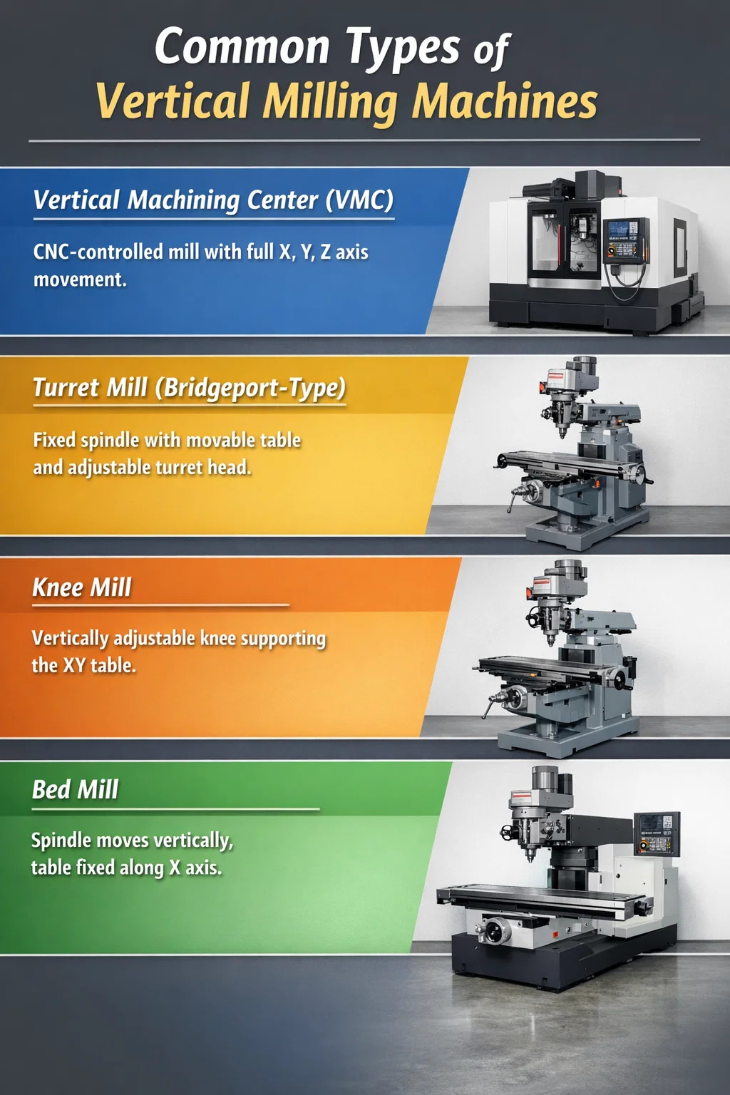
Vertical Machining Center (VMC)
This is the modern, standardized industry term for a CNC-controlled vertical milling machine. Once computer numerical control was integrated into the milling process and automatic tool changers, coolant systems, and pallet changers were added, the machines evolved beyond simple milling and became "machining centers." A VMC can perform drilling, boring, reaming, tapping, and milling in a single setup. The term is now used universally in manufacturing documentation, procurement contracts, and industry standards.
Turret Mill
A turret mill features a fixed spindle while the worktable can move both perpendicular and parallel to the spindle axis. The spindle head, mounted on a turret, allows angular positioning. This design makes turret mills highly versatile for small-batch and prototype work. Turret mills are often called Bridgeport-type mills, a name derived from the Bridgeport Machines company whose knee mill design became the industry standard reference for decades. Many manual and CNC machines still follow the Bridgeport configuration today.
Knee Mill
The term "knee mill" refers specifically to any milling machine whose XY table rides up and down the column on a vertically adjustable knee. This knee allows the operator to set the vertical height of the work surface, adding a degree of flexibility for varying part heights. Knee mills are a subcategory of turret mills and are especially common in job shops and educational environments.
Bed Mill
Unlike turret mills, bed mills have a worktable that moves only along the X-axis (perpendicular to the spindle), while the spindle head moves vertically. This configuration provides greater rigidity, which makes bed mills better suited for heavy-duty cutting and larger workpieces. Most large-format VMCs in production environments are bed-style machines.
| Name | Spindle Orientation | Table Movement | Best Use Case |
|---|---|---|---|
| Vertical Machining Center (VMC) | Vertical | X, Y, Z (CNC) | Precision production, multi-process parts |
| Turret Mill / Knee Mill | Vertical (fixed) | X, Y + knee adjustment | Small-batch, prototyping, job shops |
| Bed Mill | Vertical (moving head) | X only | Heavy-duty, large workpieces |
| CNC Gantry Milling Machine | Vertical (bridge-mounted) | X, Y, Z (large travel) | Aerospace, large structural components |
| CNC Engraving Milling Machine | Vertical (high-speed) | X, Y, Z (high precision) | Mold copper electrodes, fine detail work |
How a Vertical Milling Machine Works: The Core Mechanics
The operating principle of a vertical milling machine is straightforward. The workpiece is clamped firmly onto the machine table using a vise, fixture, or clamp setup. The cutting tool — typically an end mill, face mill, or drill — is secured in the spindle collet or tool holder. As the spindle motor drives the cutting tool to rotate at a programmed speed (measured in RPM), the CNC system moves the table and spindle head along the X, Y, and Z axes based on G-code instructions.
Because the spindle is vertical, the cutting tool plunges downward into the workpiece. This makes vertical mills particularly well-suited for operations such as:
- Face milling — flattening the top surface of a workpiece
- Pocket milling — cutting cavities or recesses into a part
- Contour milling — following a curved profile along the XY plane
- Drilling and tapping — the vertical spindle naturally aligns with drill axes
- Die sinking — machining mold cavities with high surface finish requirements
- Engraving — fine surface detail work with small-diameter tools
On CNC models, the operator programs the cutting path using CAD/CAM software, which generates the G-code sent to the machine controller. The controller then orchestrates spindle speed, feed rate, depth of cut, and tool movement simultaneously. On modern VMCs, spindle speeds commonly range from 8,000 to 15,000 RPM for standard machining, with high-speed spindles reaching 30,000 RPM or more in specialized applications.
CNC Gantry Milling Machine: The Large-Format Vertical Mill
A CNC Gantry Milling Machine is a specialized type of vertical milling machine built around a bridge-like (gantry) structure. Two vertical columns support a horizontal crossbeam that spans the width of the worktable. The spindle head is mounted on this crossbeam and can traverse across it, while the table — or the gantry itself — moves along the longitudinal (X) axis. This design allows the machine to accommodate workpieces that would be impossible to handle on a conventional VMC.
Structural Advantages of the Gantry Configuration
The gantry frame provides exceptional rigidity because the cutting forces are distributed symmetrically across both columns rather than through a single column as in a standard knee or bed mill. This structural integrity is what allows CNC gantry milling machines to cut hardened steel, titanium alloy structural parts, and large aluminum billets at high feed rates without vibration. In aerospace manufacturing, for example, gantry mills routinely machine fuselage frames and wing spars that exceed 10 meters in length.
Some gantry milling machines use a moving-table design, where the workpiece travels under the stationary gantry. Others use a moving-gantry design, where the bridge travels over a fixed table. Moving-table designs tend to offer better dynamic performance for smaller workpieces, while moving-gantry configurations are preferred when the workpiece is too heavy to accelerate — such as large welded steel structures or stone slabs weighing several tons.
CNC Gantry Milling Machine: Applications and Industries
CNC gantry milling machines are used in industries where workpiece size, mass, or both exceed the practical limits of conventional VMCs. Key application areas include:
- Aerospace and defense: machining fuselage panels, bulkheads, and structural ribs from aluminum alloy billets; tolerances as tight as ±0.01 mm are routinely held over meter-scale travel distances
- Heavy equipment manufacturing: machining engine blocks, gear housings, and structural weldments for construction machinery and industrial equipment
- Die and mold industry: large injection mold bases and die casting tools, where gantry mills rough out the bulk material before finish machining on high-speed VMCs
- Rail and shipbuilding: machining locomotive frames, ship propeller shafts, and hull structural components
- Energy sector: wind turbine hub flanges, generator frames, and large pump housings
Many modern CNC gantry milling machines feature 5-axis capability, where the spindle head can tilt and rotate in addition to the standard three linear axes. This eliminates the need to reposition large workpieces, reducing setup time and the cumulative error that multiple setups introduce. A 5-axis gantry mill can complete surfaces that would otherwise require three or four separate setups on a 3-axis machine.
Key Specifications to Evaluate
When selecting a CNC gantry milling machine, the most critical specifications include table size (typically expressed as width × length, ranging from 1.5 m × 3 m to 6 m × 20 m or larger), maximum workpiece weight capacity (ranging from 5,000 kg to over 100,000 kg for heavy-duty floor-type gantry mills), spindle power (commonly 22 kW to 90 kW), and spindle speed range. The rigidity of the linear guideways — whether box guides or linear rails — also significantly affects surface finish and dimensional accuracy in heavy cutting.
CNC Engraving Milling Machine: Precision at the Small Scale
At the other end of the size spectrum sits the CNC Engraving Milling Machine, a high-speed, high-precision vertical milling machine optimized for fine detail work. These machines occupy a distinct position between a general-purpose machining center and a dedicated engraver. They are sometimes called high-speed machines or engraving and milling centers in the industry, and their defining characteristics are a high-speed spindle, a rigid compact frame, and motion systems capable of executing very tight contouring paths accurately.
How CNC Engraving Milling Machines Differ from Standard VMCs
Standard VMCs are optimized for metal removal rate — they use larger-diameter tools, higher torque at moderate speeds, and workpiece clamping for bulk material removal. CNC engraving milling machines take the opposite approach. Their spindles typically run at 20,000 to 60,000 RPM, which allows the use of very small-diameter tools (sometimes as small as 0.1 mm) without generating the tool deflection that would occur at lower RPMs. This high rotational speed compensates for the reduced chip load per tooth, producing excellent surface finishes even in hardened steel above HRC60.
The table size on CNC engraving milling machines is deliberately smaller than on a general VMC. A typical CNC engraving milling machine table ranges from 450 mm × 450 mm to 700 mm × 620 mm, compared to a VMC whose minimum table size is generally 830 mm × 500 mm. This smaller footprint contributes to the frame rigidity needed for fine work, since a smaller machine structure has fewer compliance points where vibration can enter the cutting process.
Primary Applications of CNC Engraving Milling Machines
CNC engraving milling machines are the preferred choice across several demanding precision applications:
- Mold copper electrode machining: graphite and copper EDM electrodes require extremely fine surface quality and complex 3D geometry; a CNC engraving milling machine produces these in one setup without polishing
- Precision mold roughing and finishing: the machine can process a small mold cavity from raw stock to finished surface in one clamping, eliminating repositioning errors
- Watchmaking and jewelry: machining watch movement components, bezels, and settings in brass, stainless steel, and titanium to tolerances of ±0.002 mm
- Shoe mold manufacturing: 3D surface molds for footwear require smooth compound curves — the high-speed small-tool capability of engraving milling machines produces these without hand polishing
- Aluminum parts and fixture machining: where fine feature detail and smooth surface finish are required on aluminum structural and decorative components
- Engraving and surface decoration: text, logos, and decorative patterns on metal parts for consumer electronics, industrial nameplates, and medical devices
Material Capability: Harder Than You Might Expect
One common misconception is that CNC engraving milling machines are limited to soft materials. In practice, a well-built CNC engraving milling machine can directly process hardened tool steel above HRC60, eliminating the traditional sequence of rough milling in the annealed state, heat treating, and then finishing with grinding or EDM. This capability reduces lead time and total cost significantly for small precision molds. The key enabling factor is the combination of a rigid frame, high-speed spindle with precise dynamic balancing, and solid carbide tooling specifically designed for hard milling.
Vertical Milling Machine vs. Horizontal Milling Machine: Core Differences
Understanding what makes a vertical milling machine distinctive requires a direct comparison with its horizontal counterpart. Both machine types use a rotating cutting tool to remove material from a stationary workpiece, but the orientation of the spindle creates significant differences in cutting geometry, capability, and cost.
| Feature | Vertical Milling Machine | Horizontal Milling Machine |
|---|---|---|
| Spindle orientation | Vertical (perpendicular to table) | Horizontal (parallel to table) |
| Typical tool type | End mill, face mill, ball nose | Shell mill, side cutter, arbor cutter |
| Material removal rate | Moderate | High (thicker tools, heavier cuts) |
| Precision / fine detail | High (especially VMC and engraving) | Moderate |
| Chip evacuation | Chips fall onto workpiece (requires coolant) | Chips fall away naturally (gravity-assisted) |
| Cost | Lower initial investment | 3–4× higher than comparable vertical |
| Operator visibility | Good — spindle and workpiece clearly visible | Limited — arbor and cutter can obstruct view |
| Operator skill availability | High (more operators trained on vertical) | Lower (fewer operators experienced) |
One practical consideration that often goes unmentioned: because vertical milling machines are far more common across the manufacturing industry, the pool of trained operators is substantially larger. This reduces the HR risk of relying on specialized horizontal milling expertise, particularly for smaller shops or manufacturers in regions where CNC talent is scarce.
Choosing Between a Standard VMC, a CNC Gantry Milling Machine, and a CNC Engraving Milling Machine
The three main variants of vertical milling machines serve distinct manufacturing needs. Selecting the wrong type results in either underutilized machine capability — paying for capacity you do not need — or, more costly still, repeatedly hitting the limits of a machine that cannot meet the job requirements.
Choose a Standard CNC VMC When
- Your workpieces fit within a table travel of roughly 500–1,000 mm × 400–600 mm
- You produce a mix of prismatic parts in steel, aluminum, cast iron, or engineering plastics
- Production volumes are medium to high and require consistent dimensional repeatability
- Your shop needs a versatile general-purpose machine that can handle a wide variety of jobs without specialized tooling
Choose a CNC Gantry Milling Machine When
- Workpieces are large — exceeding 1.5 m in any linear dimension — or extremely heavy
- You work in aerospace, rail, shipbuilding, heavy equipment, or large mold manufacturing
- High material removal rates on large surfaces are required — gantry mills excel at aggressive roughing passes over long distances
- 5-axis capability is needed to machine complex large parts in a single setup
Choose a CNC Engraving Milling Machine When
- Your parts are small and require fine surface detail that a standard VMC cannot achieve without sacrificing speed
- You produce EDM electrodes (copper or graphite), small precision molds, or watch/jewelry components
- Direct hard milling of materials above HRC55 is needed, avoiding the EDM step entirely
- Engraving and fine decorative surface work on metal is a significant part of your workload
Vertical Milling Machine: Advantages That Explain Its Dominance
Vertical milling machines — in all their forms from turret mills to VMCs to CNC gantry machines — account for the majority of milling machines installed in manufacturing facilities worldwide. This dominance is not accidental. Several practical advantages reinforce the preference for vertical configurations across a wide range of industries.
Visibility and monitoring. The vertically oriented spindle and the top-down cutting approach give operators and monitoring systems a clear, unobstructed view of the cutting process. This reduces setup errors, makes it easier to detect tool wear or breakage mid-cycle, and simplifies the use of optical probes and vision systems for in-process inspection.
Versatility across operations. A single vertical milling machine can perform face milling, pocket milling, drilling, boring, reaming, tapping, contouring, and engraving without changing the fundamental machine setup. Horizontal mills, while powerful for heavy cutting and slotting, are less suited to this diverse range of single-setup operations.
Lower acquisition cost. A standard VMC costs significantly less than a comparable horizontal machining center. The cost differential is typically in the range of 3 to 4 times, which means the initial capital commitment for a vertical machine is far lower. For small and mid-sized manufacturers, this difference determines which investments are feasible.
Compact footprint. Vertical milling machines require less floor space than horizontal machines. In facilities where floor space directly translates to production capacity, this compactness allows a greater density of machine tools per square meter.
Wider tooling availability. The vertical spindle is compatible with the vast majority of cutting tool products on the market. End mills, drills, face mills, ball nose cutters, and reamers are all designed around the assumption of vertical spindle use, which means tool selection, cost, and delivery time are straightforward.
Limitations to Consider Before Investing
Despite their wide applicability, vertical milling machines have real limitations that become significant in specific contexts. Recognizing these upfront prevents costly mismatches between machine capability and production requirements.
Chip accumulation. Because the spindle cuts downward, chips tend to fall back onto the workpiece. Without adequate coolant pressure and chip conveyor systems, accumulated chips can be re-cut by the tool, shortening tool life and degrading surface finish. Horizontal milling machines have a natural advantage here, as gravity pulls chips away from the cutting zone.
Single-face access. A vertical mill naturally accesses the top face of a workpiece. Machining on the sides or bottom requires additional setups, dedicated fixturing, or 5-axis capability. For parts that need machining on all six faces, a horizontal machining center or a full 5-axis VMC may be more economical over the total production lifecycle.
Heavy workpiece handling. Raising and lowering very heavy workpieces on the table of a vertical mill can introduce fixture compliance and workpiece movement errors. Gantry-style machines partially solve this by bringing the tool to the workpiece rather than moving the workpiece to the tool, but standard vertical machining centers are not ideal for multi-ton parts.
Material removal rate ceiling. For the highest-volume, deepest-cut applications — such as roughing large gray iron castings or milling wide flat faces on structural steel — horizontal milling machines with face mills and high-power arbor configurations can outperform vertical mills in material removal rate per unit time. This gap has narrowed with high-speed machining strategies on VMCs, but it has not closed entirely.
The Evolution from Manual Knee Mill to CNC Machining Center
The history of the vertical milling machine reflects broader developments in manufacturing technology. Manual knee mills, which operators controlled entirely by hand wheels and graduated dials, were the industry standard through much of the 20th century. The introduction of digital readouts (DRO) in the 1970s improved dimensional accuracy without full automation. Early NC (numerical control) systems, which used punched tape to drive axis movement, appeared in the 1950s and 1960s but required time-consuming tape preparation for every new part.
The shift to CNC — where a computer runs part programs directly — transformed vertical milling machines from skilled manual operations into programmable production systems. Automatic tool changers eliminated manual tool swaps between operations. Pallet changers allowed one part to be loaded while another was being machined, dramatically increasing spindle utilization. Touch probes enabled in-process measurement and automatic offset correction without stopping the cycle.
The result was that the machining center — the CNC evolution of the vertical milling machine — could complete multiple processes in a single clamping that previously required moving the workpiece between several separate machines. A part that once required a milling machine, a drill press, a boring machine, and a tapping machine could now be completed on one VMC. This consolidation reduces handling time, eliminates repositioning errors, and simplifies production scheduling. Today, that same trajectory continues with multi-axis VMCs, mill-turn centers, and integrated automation systems built around what began as the basic vertical milling machine concept.
PREV:What Are CNC Machines? A Complete Guide to CNC Equipment
NEXT:What Is CNC Vertical Machining? Process, Benefits & Applications
NEXT:What Is CNC Vertical Machining? Process, Benefits & Applications
Interested in cooperation or have questions?
News
-
-
What Is CNC Programming? CNC programming is the process of writing a set of coded instructions, most commonly in G-code and M-code, that tell a computer numerical control machine exactly how a cutting tool should move to turn raw...
READ MORE -
What Is a CNC Wire Cut Machine A CNC wire cut machine is a piece of CNC Equipment that removes metal by generating controlled electrical sparks between a thin, continuously moving wire electrode and a conductive workpiece, rathe...
READ MORE -
What Is a CNC Machine? A Complete Answer A CNC machine — short for Computer Numerical Control machine — is a piece of automated manufacturing equipment that uses pre-programmed computer software to control the movement of cutti...
READ MORE
Related Products


-
Factory Address
Zhaxi Township Industrial Park, Nantong City, Jiangsu Province, China (west of Huaneng Power Plant)
-
Phone
+86-13615235768
+86-15950816906
-
Fax
+86-513-85632766
-
Email
pan.director@sunwayer.com
Stay Connected
lf you can't find the answer you're looking for, chat with our friendly team.
Stay Connected
Copyright © Nantong Sunway Science and Technology Development Co., Ltd. All Rights Reserved.
China CNC Equipment Manufacturers
Custom CNC Equipment Factory
