

 русский
 Español
What Is a CNC Wire Cut Machine A CNC wire cut machine is a piece of CNC Equipment that removes metal by generating controlled electrical sparks between a thin, continuously moving wire electrode and a conductive workpiece, rathe...
READ MORE
What Is CNC Vertical Machining? Process, Benefits & Applications
Content
- 1 What Is CNC Vertical Machining?
- 2 How a Vertical Machining Center Works
- 3 VMC vs. HMC: Key Differences
- 4 Common Machining Operations Performed on VMCs
- 5 Materials Suitable for CNC Vertical Machining
- 6 Types of Vertical Machining Centers
- 7 Advantages of CNC Vertical Machining
- 8 Limitations to Consider
- 9 Industries and Applications That Rely on Vertical Machining Centers
- 10 Selecting the Right VMC: Key Specifications to Evaluate
- 11 CNC Vertical Machining and Automation
- 12 Tolerances and Surface Finishes Achievable on VMCs
- 13 The Role of CAD/CAM in CNC Vertical Machining
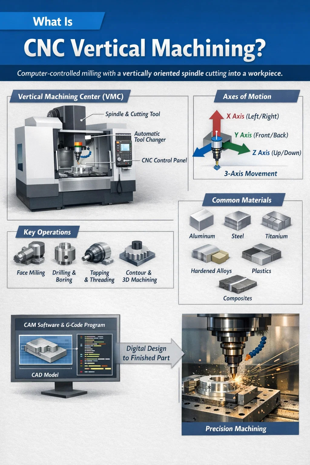
What Is CNC Vertical Machining?
CNC vertical machining is a subtractive manufacturing process in which a computer-numerically-controlled machine uses a vertically oriented spindle to drive rotating cutting tools downward into a workpiece that is held stationary on a horizontal table. The machine reads a digital program — typically G-code — and translates those instructions into precise, repeatable movements along multiple axes, removing material to produce the desired shape, feature, or surface finish.
The term "vertical" refers to the orientation of the spindle axis, which runs perpendicular to the ground. This distinguishes the process from horizontal machining, where the spindle is parallel to the floor. The vertical arrangement makes it straightforward for operators to load and inspect workpieces, and it is well-suited for flat or prismatic parts that benefit from top-down cutting forces pressing the component firmly against the table.
Vertical Machining Centers (VMCs) are the machines at the heart of this process. A VMC integrates an automatic tool changer, a coolant system, an enclosure, and CNC control into a single unit. Modern VMCs routinely achieve positional accuracies of ±0.005 mm (±0.0002 in) and can execute complex contoured surfaces, deep pockets, precision bores, and threaded features without repositioning the workpiece multiple times.
Industries ranging from aerospace and automotive to medical device manufacturing and consumer electronics rely on CNC vertical machining because it combines speed, repeatability, and geometric flexibility in a compact footprint that fits most production environments.
How a Vertical Machining Center Works
Understanding the mechanics behind a VMC helps clarify why the process delivers such consistent results across high-volume production runs and one-off prototype jobs alike.
The Spindle and Cutting Tool
The spindle is the rotating assembly that grips and drives the cutting tool. In a VMC it points straight down. Spindle speeds typically range from 50 RPM to 24,000 RPM depending on the machine's design and the material being cut. High-speed spindles above 15,000 RPM are common when machining aluminum, while lower speeds with higher torque are used for stainless steel or titanium. The spindle taper — commonly BT30, BT40, HSK-A63, or CAT40 — determines the tool-holding interface and influences rigidity.
Axes of Motion
A standard VMC operates on three linear axes:
- X-axis — left-to-right movement of the table or spindle head
- Y-axis — front-to-back movement
- Z-axis — up-and-down movement of the spindle
4-axis and 5-axis VMCs add rotational axes — typically a rotary A-axis (tilting around X) and a B- or C-axis (rotation around Y or Z). Five-axis simultaneous machining lets the cutting tool approach the workpiece from virtually any angle in a single setup, which is critical for turbine blades, orthopedic implants, and complex mold geometries.
Automatic Tool Changer (ATC)
Most VMCs carry between 20 and 60 tools in a carousel or chain-type magazine. When the CNC program calls for a new tool, the ATC swaps it in typically within 2–5 seconds, allowing the machine to drill, mill, bore, tap, and ream without operator intervention between operations. High-capacity machines for complex aerospace parts may hold more than 120 tools.
The CNC Control System
The controller — common brands include Fanuc, Siemens Sinumerik, Heidenhain, and Mitsubishi — interprets the G-code program and coordinates servo motor movements with microsecond precision. Modern controllers support features such as tool life management, adaptive feed rate control, in-process probing, and wireless DNC (Direct Numerical Control) connectivity to factory networks. CAM (Computer-Aided Manufacturing) software generates the G-code from a 3D CAD model, translating design intent directly into machine motion.
Workholding and Fixturing
Parts are secured to the table using vises, clamps, modular fixturing systems, vacuum chucks, or dedicated custom fixtures. Proper workholding is critical: even a 0.02 mm shift in a fixture under cutting forces can push a precision feature outside tolerance. Zero-point clamping systems from manufacturers such as Schunk and Erowa allow palletized workpieces to be exchanged in under 30 seconds with repeatability below 0.005 mm, enabling lights-out automation.
VMC vs. HMC: Key Differences
Vertical Machining Centers and Horizontal Machining Centers (HMCs) share the same CNC foundation but differ in spindle orientation, chip evacuation, and optimal use cases. The table below summarizes the most relevant distinctions for buyers and process planners.
| Criterion | Vertical Machining Center (VMC) | Horizontal Machining Center (HMC) |
|---|---|---|
| Spindle orientation | Vertical (Z points down) | Horizontal (Z points sideways) |
| Chip evacuation | Chips accumulate on part; coolant flush needed | Chips fall away by gravity — superior |
| Ideal workpiece type | Flat, prismatic, medium-complexity parts | Cube-shaped, heavy, multi-sided parts |
| Machine footprint | Compact — fits smaller shops | Larger — requires more floor space |
| Purchase cost (typical entry-level) | $50,000–$200,000 | $150,000–$600,000+ |
| Operator visibility | Excellent — easy to see the cutting zone | Limited — enclosed spindle head |
| Pallet automation | Available but less common at entry level | Standard on most HMCs |
For most job shops and contract manufacturers producing parts with features primarily on one face, a VMC delivers the best balance of capability, cost, and ease of use. HMCs become more economical when running high volumes of complex four-sided parts where reduced setup time justifies the higher capital investment.
Common Machining Operations Performed on VMCs
Vertical Machining Centers are not single-purpose machines. Because the tool magazine can carry dozens of different cutting tools, a single program can chain together multiple operations in one continuous cycle.
Face Milling and Peripheral Milling
Face milling uses large-diameter insert cutters to flatten surfaces quickly and achieve low roughness values — typically Ra 0.8–3.2 µm — in a single pass. Peripheral milling (side milling) produces vertical walls, steps, and profiles by engaging the side flutes of an end mill. Together these two operations form the backbone of most prismatic part programs.
Drilling and Boring
Twist drills, spot drills, and carbide spade drills produce round holes. Toleranced bores that must meet H7 or tighter fits are then finished with a boring head, which can achieve diameters accurate to ±0.005 mm. High-precision bores for bearing seats, valve bodies, and hydraulic manifolds rely on single-point boring tools fed at slow, controlled rates.
Tapping and Thread Milling
Rigid tapping synchronizes spindle rotation with Z-axis feed to cut internal threads. Thread milling — where a multi-flute thread mill traces a helical path — offers the advantage of producing any thread diameter with a single tool and allows thread depth and fit class to be adjusted in the CAM program without changing tools. This is especially useful for large-diameter threads or threads in hard materials where tap breakage would be costly.
Contour Milling and 3D Surface Machining
Ball-nose end mills trace contoured toolpaths to produce curved surfaces, fillets, and organic shapes. CAM software calculates thousands of closely spaced passes — stepover values of 0.1–0.5 mm are common in finishing passes — to build up a smooth surface. Injection mold cavities, die-cast tooling, and orthopedic bone implants are examples where 3D surface machining on a VMC is indispensable.
Engraving and Pocketing
Small-diameter end mills and engraving tools produce part numbers, logos, alignment features, and complex internal pockets. Trochoidal milling toolpaths — where the cutter follows a circular arc while advancing — reduce cutting forces and allow higher feed rates in deep pocket machining, cutting cycle times by 30–50% compared to conventional straight-line passes in hard materials.
Materials Suitable for CNC Vertical Machining
VMCs can cut nearly any engineering material, provided the spindle speed, feed rate, depth of cut, and tooling are chosen appropriately. The following materials represent the most common workpieces processed on Vertical Machining Centers.
- Aluminum alloys (6061, 7075, 2024): The most frequently machined metal on VMCs. Aluminum cuts quickly at high spindle speeds, produces long chips, and responds well to flood coolant. Typical cutting speeds exceed 500 m/min in finishing passes.
- Steel (mild, tool steel, stainless): Requires lower cutting speeds, higher torque, and often coated carbide or cermet tooling. 304 stainless steel is notorious for work hardening, demanding sharp tools and consistent chip loads to avoid rubbing.
- Titanium (Ti-6Al-4V): Low thermal conductivity means heat concentrates at the cutting edge. VMC programs for titanium use conservative depths of cut, high-pressure coolant directed exactly at the cutting zone, and premium coated carbide end mills.
- Hardened tool steels and Inconel: Requires CBN (Cubic Boron Nitride) inserts or high-performance carbide grades. Cutting speeds may be as low as 20–50 m/min, but the ability to machine parts to near-net shape and then hard-mill them in the same VMC eliminates separate grinding operations.
- Engineering plastics (Delrin, PEEK, nylon, UHMW-PE): Low cutting forces allow high feed rates. Sharp tools and minimal coolant (compressed air is often preferred) prevent melting and built-up edge. Common in medical device and food-processing equipment manufacturing.
- Carbon fiber and composites: Abrasive, delamination-prone, and produces hazardous dust requiring proper extraction. Diamond-coated router bits and VMC spindles capable of 18,000+ RPM are preferred for CFRP components used in aerospace and sporting goods.
Types of Vertical Machining Centers
Not all VMCs are configured the same way. Machine builders offer a range of architectures to address different part sizes, production volumes, and precision requirements.
Knee-Type VMC
An older design in which the table rides on a vertically adjustable knee. Common in toolrooms and educational settings but lacks the rigidity and speed of fixed-column designs for production work. Table travel is limited, and the knee introduces compliance under heavy cutting forces.
Fixed-Column (Bridge) VMC
The most common design in production environments. The column is fixed to the base casting, and the spindle head moves in X, Y, and Z. Tables sizes from 500 mm × 400 mm up to 2,500 mm × 700 mm cover the majority of aerospace frames, automotive transmission cases, and mold blocks encountered in industry.
Double-Column (Gantry) VMC
Two columns straddle the table and support a crossrail from which the spindle head travels. This arrangement provides exceptional rigidity for very large, heavy workpieces. Gantry VMCs are used to machine aircraft structural panels — some machines handle workpieces over 5 meters long — and large power generation components.
5-Axis VMC
Adds a tilting-rotary table or a swiveling spindle head to the standard three linear axes. The additional degrees of freedom allow undercut features, compound angles, and complex freeform surfaces to be cut without re-fixturing. Five-axis VMCs are now standard in aerospace subcontracting and medical implant manufacturing. Entry-level five-axis machines from brands such as Haas, DMG Mori, Mazak, and Okuma start around $200,000–$350,000.
Micro-VMC
Designed for miniature components in the watch, electronics, and medical micro-device sectors. Micro-VMCs run spindles at 50,000–100,000 RPM with micro-diameter end mills as small as 0.1 mm. Thermal stability of the machine structure is paramount at this scale, and many micro-VMCs incorporate active thermal compensation systems.
Advantages of CNC Vertical Machining
The widespread adoption of Vertical Machining Centers across industries is not accidental. The process offers a well-established combination of practical benefits that make it the default choice for a broad range of precision components.
High Dimensional Accuracy and Repeatability
Ball-screw drives with linear encoders allow modern VMCs to position axes to within ±0.001 mm, and some high-precision machines achieve sub-micron repeatability. Once a program is proven, the machine can reproduce the same part geometry across thousands of cycles with statistically identical results — a prerequisite for interchangeable assembly in automotive and aerospace production.
Lower Setup Time Compared to Conventional Machining
Because the CNC program stores all tool offsets, feed rates, and spindle speeds, repeated setups for the same part require only fixture loading and program recall. A setup that might take a skilled manual machinist four hours can be reduced to 15–30 minutes on a VMC with a proven fixture and program.
Multi-Operation Capability in One Setup
The combination of an automatic tool changer and rigid workholding means that drilling, milling, tapping, boring, and engraving can all happen in sequence without moving the part. Eliminating inter-operation transfers removes datum shift errors that accumulate when parts are moved between machines, and it cuts work-in-progress queue time dramatically.
Ease of Operation and Visibility
The vertical spindle orientation gives operators a direct sightline into the cutting zone through the machine's window. Loading flat or block-shaped workpieces onto a horizontal table is intuitive and requires no overhead lifting or special fixtures simply to orient the part. This visibility also simplifies in-process probing and first-article inspection.
Compact Floor Footprint
A standard production VMC with a 762 mm × 406 mm table typically occupies a floor area of roughly 2.5 m × 2.0 m, making it feasible to install multiple machines in a shop with modest floor space. This density advantage supports cellular manufacturing layouts where one operator manages two or three VMCs simultaneously.
Cost-Effectiveness for Low to Medium Volumes
VMCs represent the lowest capital entry point into precision CNC machining. A capable three-axis VMC from Haas Automation, Fanuc Robodrill, or Brother can be purchased new for $50,000–$130,000, a fraction of the cost of a comparable HMC or multi-pallet machining cell. For job shops running batches of 1–500 parts, this cost structure is highly competitive.
Limitations to Consider
No machining process is optimal for every application. CNC vertical machining has specific constraints that engineers and buyers should weigh honestly.
- Chip accumulation on the part: Gravity pulls chips downward onto the workpiece, where they can be re-cut, scratch finished surfaces, or interfere with probing. High-pressure through-spindle coolant and strategic coolant nozzle placement mitigate this, but chip management requires more attention than on horizontal machines.
- Limited access to side and bottom features: Without rotary axes, a standard 3-axis VMC can only cut features on the top face of a workpiece in a single setup. Parts requiring machining on four or five faces must be repositioned, adding setup time and introducing potential datum errors at each flip.
- Long overhang and deep pocket challenges: Tall thin features and deep pockets force the use of long-reach tools that deflect under cutting forces, reducing accuracy and limiting achievable feed rates. Aspect ratios beyond 6:1 (depth to diameter) are difficult to hold to tight tolerances on a VMC.
- Thermal growth: Spindle heat and ambient temperature changes cause measurable dimensional drift over a shift. High-end VMCs incorporate thermal compensation algorithms, but budget machines may need warm-up cycles and periodic re-probing to maintain tight tolerances across long production runs.
- Lower productivity for high-volume cubic parts: When a component needs four or five faces machined, an HMC with a pallet changer can complete more parts per shift because the pallet system loads a new part while the previous one is still being cut. For volumes above roughly 10,000 identical cubic parts per year, the HMC's economics often surpass the VMC's.
Industries and Applications That Rely on Vertical Machining Centers
The flexibility of CNC vertical machining has made VMCs indispensable across sectors that demand accuracy, material variety, and the ability to produce low-to-medium volumes economically.
Aerospace and Defense
Structural brackets, avionics housings, fuel system manifolds, and landing gear components are routinely produced on VMCs. Aerospace tolerances are demanding — positional tolerances of ±0.025 mm or tighter, surface finishes below Ra 0.8 µm, and full dimensional reports on every part are the norm. Five-axis VMCs have displaced dedicated transfer line equipment in many aerospace supply chains because they can process complex geometry without dedicated tooling for each feature.
Automotive
Prototype and low-volume automotive parts — engine blocks, cylinder heads, transmission housings, suspension knuckles — are machined on VMCs during development phases before being transferred to dedicated machining lines for mass production. EV (electric vehicle) programs drive demand for machined battery enclosures, heat exchanger plates, and motor housings, most of which are aluminum and well-suited to VMC processing.
Medical Device and Implant Manufacturing
Orthopedic implants (knee tibial trays, femoral components, spinal cages), surgical instruments, and diagnostic device housings require biocompatible materials, excellent surface finishes, and tight tolerances. Five-axis VMCs machine titanium and cobalt-chrome implants to ISO 13485 quality system requirements with full traceability from raw material to finished part.
Tooling and Mold Making
Injection mold cavities, die-casting tooling, blow molds, and stamping dies are almost universally roughed and finished on VMCs. High-speed VMCs with spindles above 20,000 RPM can machine hardened P20 or H13 tool steel at Rc 50–60, eliminating EDM operations for many cavity features and dramatically shortening mold lead times.
Electronics and Semiconductor Equipment
Wafer chuck bodies, vacuum manifolds, heat sinks, and enclosures for test-and-measurement equipment are machined from aluminum, copper, and engineered plastics on VMCs. The electronics industry's drive toward miniaturization increases demand for micro-VMCs and high-speed spindles that can process features measured in tens of microns.
Energy and Oil and Gas
Valve bodies, flow control manifolds, pump housings, and flange components for the oil and gas industry are machined on large-bed VMCs from stainless steel and duplex alloys. The sector demands full material certifications, pressure test records, and in many cases third-party NDT inspection, all of which integrate into quality management workflows alongside the VMC's production data.
Selecting the Right VMC: Key Specifications to Evaluate
Choosing a Vertical Machining Center is a capital investment that should align with the specific parts you plan to produce. Comparing machines on the following parameters will narrow the field systematically.
| Specification | Typical Range | Why It Matters |
|---|---|---|
| Table size (X × Y travel) | 400×300 mm to 2,500×700 mm | Determines maximum workpiece envelope |
| Z-axis travel | 300–800 mm | Limits maximum workpiece height plus fixture height |
| Spindle speed | 4,000–24,000 RPM | Higher speeds needed for aluminum and small-diameter tools |
| Spindle power | 7–37 kW | Determines metal removal rate in heavy cuts |
| Rapid traverse rate | 24–60 m/min | Affects cycle time on parts with many repositioning moves |
| Tool magazine capacity | 16–120 tools | Larger magazines reduce tool change interruptions in complex programs |
| Positioning accuracy | ±0.002–±0.010 mm | Directly limits the tightest tolerances the machine can hold |
| Coolant pressure | 20–80 bar (through-spindle) | High pressure essential for deep drilling and difficult materials |
Beyond specifications, evaluate the builder's service network (mean time to repair is critical for production continuity), the availability of software integrations (ERP, DNC, MES), and the ease of programming on the specific CNC control. A machine from a brand with strong local applications engineering support will often outperform a technically superior machine from a brand with poor regional service coverage.
CNC Vertical Machining and Automation
VMCs are increasingly integrated into automated cells that extend their productive hours beyond standard shifts. Several automation architectures are in common use.
Robotic Part Loading
A six-axis collaborative or industrial robot positioned beside the VMC picks raw stock from an input tray, places it in the machine's vice, and retrieves the finished part to an output conveyor. Collaborative robots (cobots) from Universal Robots, FANUC, and KUKA allow integration without safety fencing in many configurations, and payback periods of 12–18 months are achievable for cells running high-volume repeat parts.
Pallet Pool Systems
Pallet pools (Systems 3R, Erowa, Schunk) store multiple pre-fixtured workpieces. A stacker crane or robot retrieves pallets from the pool and loads them into the VMC's zero-point clamping system. The machine can then run unattended overnight, completing dozens of different part programs from a queue, with each pallet's program called up automatically via an RFID chip or barcode. This approach is common in mold shops and job shops that run high-mix, medium-volume work.
In-Process Probing and SPC Integration
On-machine probing systems (Renishaw, Heidenhain) measure critical features between operations, automatically updating tool offsets to compensate for wear. Statistical Process Control (SPC) software connected to the VMC's controller logs measurement data in real time, alerting operators when a trend approaches a tolerance boundary before out-of-tolerance parts are produced. This closed-loop approach reduces scrap rates to below 0.5% in well-run cells.
Tolerances and Surface Finishes Achievable on VMCs
A practical question for engineers designing parts is what tolerance grades and surface finishes can reliably be held on a production VMC. The answer depends on machine quality, tooling, fixturing, and material, but the following benchmarks apply to well-maintained production Vertical Machining Centers.
- Linear dimensions: ±0.025 mm (±0.001 in) is achievable on most production VMCs without special measures. High-precision VMCs with linear glass scales and thermal compensation can hold ±0.005 mm or better.
- Bore tolerances: H7 fits (±0.010–0.025 mm depending on diameter) are routine using carbide boring heads. H6 fits require careful thermal management and are achievable on precision VMCs.
- Surface finish — milled surfaces: Ra 1.6–3.2 µm in standard production milling, Ra 0.4–0.8 µm with sharp finishing end mills and light passes, Ra 0.2 µm or better with diamond-cut finishing on aluminum.
- Flatness and parallelism: 0.01–0.02 mm across a 300 mm span on quality VMCs using fly-cut operations.
- Thread quality: 6H class threads (the standard for general engineering threads) are easily achieved by rigid tapping. Thread milling can produce 4H class threads in hard or exotic materials where tap breakage makes rigid tapping impractical.
When tighter tolerances than the above are required, VMC operations can be followed by cylindrical grinding, honing, lapping, or EDM. The VMC still provides the bulk of material removal and geometric shaping, leaving only a thin stock allowance for the finishing operation, which maximizes overall efficiency.
The Role of CAD/CAM in CNC Vertical Machining
Modern CNC vertical machining is inseparable from CAD/CAM software. The process begins the moment a designer creates a 3D model in software such as SolidWorks, CATIA, Siemens NX, or Autodesk Inventor. That model is then imported into a CAM package — Mastercam, Hypermill, Fusion 360, Siemens NX CAM, or similar — where a programmer defines the workholding orientation, selects tools from a digital library, assigns toolpaths to each feature, and simulates the result to check for collisions and verify material removal.
CAM simulation catches gouge errors, holder-to-fixture collisions, and excessive tool deflection before any metal is cut, reducing first-article failures significantly. Post-processors translate the CAM output into machine-specific G-code. A well-configured post-processor for a particular VMC and control combination eliminates manual G-code editing almost entirely, reducing programming errors and shortening setup time.
Advanced CAM strategies such as high-efficiency milling (HEM) — also marketed as dynamic milling, trochoidal milling, or VoluMill — maximize tool engagement and material removal rates while keeping cutting forces constant, extending tool life by 2–5 times compared to conventional toolpaths. For a shop consuming $50,000 in tooling annually, adopting HEM strategies across all VMC programs could reduce that cost to $10,000–$25,000 without purchasing a single new machine.
PREV:What Is a Vertical Milling Machine Also Known As? VMC Guide
NEXT:What Tooling Is Used in Vertical Milling? Complete Guide
NEXT:What Tooling Is Used in Vertical Milling? Complete Guide
Interested in cooperation or have questions?
News
-
-
What Is a CNC Machine? A Complete Answer A CNC machine — short for Computer Numerical Control machine — is a piece of automated manufacturing equipment that uses pre-programmed computer software to control the movement of cutti...
READ MORE -
CNC Equipment Guide What Direction Is the Z Axis on a CNC Machine? On virtually every CNC machine, the Z axis runs perpendicular to the work surface — pointing straight up and down relative to the table. Positive Z moves the spi...
READ MORE -
What Manufacturing Design Actually Means Manufacturing design is the stage of product development where a concept is converted into a buildable specification — a set of drawings, tolerances, material callouts, and process notes t...
READ MORE
Related Products


-
Factory Address
Zhaxi Township Industrial Park, Nantong City, Jiangsu Province, China (west of Huaneng Power Plant)
-
Phone
+86-13615235768
+86-15950816906
-
Fax
+86-513-85632766
-
Email
pan.director@sunwayer.com
Stay Connected
lf you can't find the answer you're looking for, chat with our friendly team.
Stay Connected
Copyright © Nantong Sunway Science and Technology Development Co., Ltd. All Rights Reserved.
China CNC Equipment Manufacturers
Custom CNC Equipment Factory
