

 русский
 Español
What Is a CNC Wire Cut Machine A CNC wire cut machine is a piece of CNC Equipment that removes metal by generating controlled electrical sparks between a thin, continuously moving wire electrode and a conductive workpiece, rathe...
READ MORE
What Tooling Is Used in Vertical Milling? Complete Guide
Content
- 1 The Core Answer: What Tooling Does Vertical Milling Actually Use?
- 2 End Mills: The Workhorse of Vertical Machining Centers
- 3 Face Mills and Shell Mills: Rapid Surface Generation
- 4 Drilling Tools Used in Vertical Milling Operations
- 5 Boring Tools: Achieving Precision Hole Diameters on VMCs
- 6 Reamers: Final Sizing for Close-Tolerance Holes
- 7 Tapping and Thread Milling on Vertical Machining Centers
- 8 Tool Holders: Connecting Tooling to the VMC Spindle
- 9 Specialized Milling Cutters for Vertical Machining Centers
- 10 Tooling for High-Speed Machining on Modern VMCs
- 11 Tooling Management Strategies for Vertical Machining Centers
- 12 Summary Comparison of Common VMC Tooling by Operation
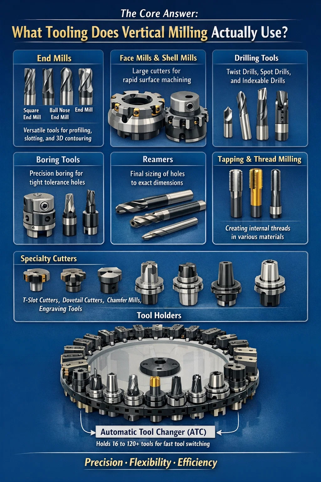
The Core Answer: What Tooling Does Vertical Milling Actually Use?
Vertical milling relies on a broad family of rotating cutting tools mounted in a spindle that moves perpendicular to the worktable. The most commonly used tooling includes end mills, face mills, drill bits, boring bars, reamers, taps, and slot drills. On modern Vertical Machining Centers (VMCs), these tools are loaded into an automatic tool changer (ATC) carousel that can hold anywhere from 16 to 120+ tools, enabling complex multi-operation parts to be completed in a single setup.
The choice of tooling is never arbitrary. Each cutting tool is selected based on the workpiece material, the type of operation (roughing, finishing, profiling, drilling), the machine's spindle speed and horsepower, and the required surface finish or dimensional tolerance. A shop running aluminum aerospace components will equip their VMC very differently from one machining hardened tool steel mold cavities.
Understanding the full tooling ecosystem of vertical milling is essential for anyone specifying a VMC, programming CNC operations, or managing a machine shop. Below is a deep and structured breakdown of every major tool category, how they work, when to use them, and what specifications matter most.
End Mills: The Workhorse of Vertical Machining Centers
End mills are the most versatile and widely used cutting tools on any VMC. Unlike drill bits that only cut axially, end mills cut both axially and radially, which allows them to perform side milling, slotting, contouring, ramping, and even helical interpolation for hole-making. They are the tool you reach for first in most vertical milling operations.
Flute Count and Its Effect on Cutting Performance
End mills are categorized primarily by their number of flutes. A 2-flute end mill has large chip gullets and is the standard choice for aluminum and soft non-ferrous materials where chip evacuation is critical. A 4-flute end mill offers more cutting edges and better surface finish, making it the default for steel and stainless steel. High-performance end mills with 5, 6, 7, or even 9 flutes are used for high-speed finishing of hardened steels above 50 HRC, where small chip loads distributed across many flutes reduce deflection and improve finish quality dramatically.
In practical terms, a 4-flute carbide end mill running in mild steel (1018) at 300 SFM might take a 0.020" depth of cut at 0.002" chip load per tooth. The same cutter in 6061 aluminum could run at 1,200 SFM with a 0.005" chip load — a five-fold increase in surface footage that dramatically shortens cycle time.
End Mill Geometry Variations
- Square end mills — flat bottom, used for slots, shoulders, and general profiling. The standard geometry for most applications.
- Ball nose end mills — hemispherical tip, essential for 3D contouring, sculpted surfaces, and mold cavities on VMCs. Step-over distance and ball radius together determine scallop height on curved surfaces.
- Corner radius end mills — a small radius (typically 0.005"–0.125") at the corner reduces stress concentration, extends tool life significantly compared to sharp corners, and is preferred for roughing steel and stainless.
- Tapered end mills — conical profile for draft angles in mold machining, deep rib milling, and undercut avoidance.
- Roughing end mills (corncob style) — serrated cutting edges that break chips into small pieces, allowing very aggressive material removal rates in steel with lower cutting forces.
Substrate and Coating
Solid carbide end mills dominate modern VMC tooling because carbide is approximately three times stiffer than high-speed steel (HSS), which reduces deflection and permits much higher cutting speeds. Coatings further extend tool life: TiAlN (Titanium Aluminum Nitride) handles heat exceptionally well and is the standard for steel and cast iron. ZrN (Zirconium Nitride) and uncoated polished carbide are preferred for aluminum since TiAlN can cause built-up edge in aluminum. AlTiN variants offer oxidation resistance up to 1,472°F (800°C), useful for dry machining of hardened steels.
Face Mills and Shell Mills: Rapid Surface Generation
Face mills are large-diameter tools designed to machine flat surfaces across wide areas in a single pass. They mount directly to the VMC spindle via a stub arbor and use indexable carbide inserts rather than a solid cutting edge. Diameters typically range from 2" to 8" or larger, and insert counts range from 4 to 16 or more.
On a vertical machining center, a 4" face mill with 6 inserts can remove a 0.100" depth of cut across a 3.5" wide surface in a single pass, generating a flat, consistent finish. This is far more efficient than end milling the same surface, which would require multiple passes and leave cutter marks from the tool path.
Insert Geometry and Lead Angle
The lead angle of a face mill significantly affects chip thickness, cutting force direction, and insert life. A 45-degree lead angle face mill is the most common, directing forces at 45° into the spindle and workpiece, which reduces vibration. A 90-degree (square shoulder) face mill produces a true 90° wall and is used when a shoulder is required. High-feed mills with very low lead angles (around 10–17°) allow extremely high feed rates — sometimes exceeding 300 IPM — by converting depth of cut into thinner, wider chips, dramatically reducing axial force on the spindle.
Shell Mills vs. Face Mills
Shell mills are a subset of face mills that mount on a separate arbor and use brazed or indexable carbide teeth. They are typically used for lighter facing, side milling, and step machining. The distinction is largely one of mounting: face mills use a flange mount, shell mills use a bore-and-keyway arbor mount. On a VMC with a CAT40 or BT40 spindle taper, both types are common and often interchangeable in function.
Drilling Tools Used in Vertical Milling Operations
Drilling is a fundamental operation on vertical machining centers. The VMC's rigid spindle, precise Z-axis control, and flood coolant delivery make it highly capable for producing accurate holes quickly. The drilling tooling family includes twist drills, spot drills, center drills, indexable drills, and step drills.
Spot Drills and Center Drills
Spot drills (typically 90° or 120° point angle) are used before twist drilling to create a small conical indentation that guides the drill and prevents walking. On a VMC with accurate positioning, spot drilling is sometimes skipped in favor of peck drilling or helical interpolation, but it remains standard practice in tight-tolerance hole work. Center drills serve a similar function but also create a lathe center seat; they are less preferred for hole starting in modern VMC work due to their tendency to break under side load.
Solid Carbide Drills vs. HSS Drills
High-speed steel (HSS) twist drills remain in use for soft materials and occasional production, but solid carbide drills have become the dominant choice in VMC production environments. Carbide drills can run at 3–5× the cutting speed of HSS, produce better hole quality, and maintain tighter diameter tolerances. A solid carbide drill in 316 stainless steel might run at 200 SFM with a feed of 0.004" per revolution — values that would destroy an HSS drill rapidly.
Indexable Insert Drills
For diameters above about 0.75" (19 mm), indexable drills with replaceable carbide inserts become economically and practically superior to solid drills. These tools use two inserts positioned at different radii — one covering the center, one covering the outer zone — with different geometries to account for the varying cutting speed across the drill radius. Indexable drills can achieve metal removal rates 2–4× higher than equivalent solid drills in steel and are widely used on VMCs for large-diameter holes in production environments.
Gun Drills for Deep Holes
When hole depth exceeds 5× the diameter, standard drills struggle with chip evacuation and straightness. Gun drills — single-flute tools with internal coolant delivery through the drill body — are used on VMCs equipped with high-pressure coolant systems (typically 300–1,000 PSI). They can achieve depth-to-diameter ratios of 30:1 or more in steel, producing very straight, well-finished holes used in mold cooling channels, hydraulic manifolds, and firearm components.
Boring Tools: Achieving Precision Hole Diameters on VMCs
When a drilled or interpolated hole needs to meet a tight dimensional tolerance — say, H7 fit at ±0.0005" — boring is the operation of choice. Boring uses a single-point tool rotated by the VMC spindle to enlarge and true up an existing hole. The key advantage over drilling is that boring corrects the hole's position and cylindricity, not just its diameter.
Boring Heads
A boring head mounts to the VMC spindle (via a CAT, BT, or HSK taper) and holds a replaceable carbide boring bar or insert cartridge. The critical feature is the fine-adjustment mechanism: a micrometer-style dial on the boring head adjusts the radial position of the cutting tip in increments as small as 0.0001" (0.0025 mm). A machinist dials in the precise diameter needed by measuring a test cut and adjusting accordingly. Boring heads from manufacturers like Wohlhaupter, Sandvik Coromant, and Big Kaiser are calibrated to ±0.00008" adjustability.
Single-Point vs. Twin-Cutter Boring
Standard boring heads use a single cutting point. For higher productivity, twin-cutter or double-insert boring tools place two inserts 180° apart, doubling the feed rate while keeping balanced cutting forces. These are used in production boring of cast iron housings, engine blocks, and hydraulic manifolds where cycle time is critical.
Back Boring
Back boring — enlarging the far end of a through-hole from the entry side — is a specialized operation enabled by boring heads with offset capability. The tool enters the hole at the minimum diameter, the head is shifted radially by the CNC program, and the tool is retracted to cut the back face. This eliminates the need to flip the part for access and is critical in aerospace and valve body machining.
Reamers: Final Sizing for Close-Tolerance Holes
Reaming is the operation of finishing a drilled hole to a precise diameter and excellent surface finish — typically Ra 0.8–1.6 µm — using a multi-flute reamer. Reamers are not designed to remove much material; a typical reaming allowance is only 0.005"–0.015" (0.13–0.38 mm) on the diameter. Their purpose is to bring a pre-drilled hole to H7 or H6 fit tolerances that are impossible to achieve consistently with a drill alone.
Types of Reamers Used in VMC Work
- Hand reamers — tapered lead for manual use; rarely used on VMCs.
- Machine reamers — straight or spiral flutes, designed for VMC spindle rotation. Spiral-flute reamers are preferred for interrupted cuts and blind holes.
- Carbide reamers — solid carbide or carbide-tipped, for production work in hardened materials and long-run applications.
- Adjustable reamers — allow diameter adjustment within a small range (typically ±0.005"), useful for non-standard sizes.
Reaming on a VMC is typically performed with flood coolant and at cutting speeds 50–70% of those used for drilling the same material. Running too fast causes heat buildup that expands the reamer and produces an oversized hole; running too slow can cause chatter and poor finish.
Tapping and Thread Milling on Vertical Machining Centers
Threading is one of the most frequent operations in general machining, and vertical machining centers handle it in two fundamentally different ways: rigid tapping and thread milling. Each has specific tooling requirements and applications.
Rigid Tapping
Modern VMCs with rigid tapping capability synchronize the spindle rotation precisely with the Z-axis feed, allowing taps to be driven at controlled chip loads without a floating tapholder. Spiral-point (gun) taps push chips ahead of the tap and are ideal for through-holes. Spiral-flute taps pull chips up and out, making them the correct choice for blind holes. Form taps (roll taps) cold-form threads by displacing material without cutting, producing stronger threads and eliminating chips entirely — they require 30–40% more torque but are the preferred choice for ductile materials like aluminum and mild steel.
Tap breakage is one of the most expensive problems in machining because a broken tap in hardened material can be nearly impossible to remove. Carbide taps, proper speed/feed selection, and appropriate cutting fluid reduce this risk substantially. In 6061 aluminum, a M8×1.25 spiral-point tap might run at 60 RPM with neat cutting oil; in 304 stainless steel, the same tap would require sulfurized cutting oil and much more conservative parameters.
Thread Milling
Thread mills are multi-tooth cutters that produce threads through helical interpolation — the VMC simultaneously moves the X, Y, and Z axes in a helix while the cutter rotates. The advantages are significant: a single thread mill covers a range of thread sizes (within limits), there is no risk of catastrophic tool breakage because the cutting forces are low, and threads can be produced in very hard materials (50+ HRC) where tapping is impractical. Thread milling is also the only practical way to produce large-diameter internal threads (above about 1") on a VMC without special equipment. The tradeoff is longer cycle time and a more complex CAM program.
Tool Holders: Connecting Tooling to the VMC Spindle
The tool holder is the interface between the VMC's spindle taper and the cutting tool. It is often overlooked but has a major impact on runout, rigidity, tool life, and surface finish. On a VMC producing parts to ±0.001" tolerances, a tool holder with 0.002" TIR (total indicator runout) at the cutting edge is already consuming 20% of the entire tolerance budget before any other error source is considered.
Spindle Taper Standards
Most vertical machining centers use one of the following spindle interface standards:
| Taper Standard | Region of Origin | Typical Machine Size | Key Characteristic |
|---|---|---|---|
| CAT40 | USA | Mid-size VMC | Most common in North America; 7:24 taper |
| CAT50 | USA | Large VMC / HMC | Heavier cuts, lower spindle speed typically |
| BT30 / BT40 | Japan | Small to mid-size VMC | Balanced pull-stud design; common in Asia/Europe |
| HSK-A63 | Germany | High-speed VMC | Hollow taper; contact on both taper and face; superior rigidity at high RPM |
| Capto (C5, C6) | Sweden (Sandvik) | Turning/milling centers | Polygon taper; excellent torque transmission; used in mill-turn centers |
Types of Tool Holders for VMC Applications
- ER collet chucks — the most versatile. ER11, ER16, ER25, ER32, and ER40 collet sizes cover shank diameters from 1 mm to 26 mm. Runout on quality ER chucks is typically 0.0004"–0.0008" (10–20 µm) at the collet face.
- Hydraulic chucks — use hydraulic pressure to grip the tool shank with very high clamping force and consistently achieve runout below 0.0002" (5 µm). The preferred holder for finish milling, reaming, and high-speed operations.
- Shrink-fit holders — the tool shank is thermally expanded by induction heating, inserted, and shrinks to grip as it cools. Runout is typically 0.0001" or better (3 µm), with excellent balance for high-speed spindles above 15,000 RPM.
- Milling chucks (Weldon flat / side-lock) — a set screw engages a flat on the tool shank. Simple and rigid, but high runout and limited to lower-speed, heavier cutting applications.
- Shell mill arbors — specifically for mounting face mills and shell mills; provide a large, flat face contact for the cutter body.
- Boring head adapters — precision arbors that accept the boring head body and provide the correct register diameter and face contact.
Specialized Milling Cutters for Vertical Machining Centers
Beyond the fundamental categories, a wide range of specialized cutters extends what vertical machining centers can accomplish without secondary operations on other machines.
T-Slot Cutters
T-slot cutters machine the characteristic T-shaped slots used in machine tool tables, fixture plates, and clamping systems. They consist of a side-and-face cutter mounted on a reduced-diameter shank. After an end mill cuts the vertical slot, the T-slot cutter enters to widen the base. This is a delicate operation because the cutter is buried in the workpiece with limited chip clearance — slow feeds, sharp inserts, and abundant coolant are essential.
Dovetail Cutters
Dovetail cutters produce the angled undercut profiles used in sliding dovetail joints, guide rails, and certain fixture features. They are available in 45°, 60°, and custom angle configurations. Because the cutting edge is angled and the tool diameter must fit through a narrower slot, these tools are particularly sensitive to runout and require very precise setup. Typical applications include machine tool dovetail slides, woodworking fixture parts, and precision assembly alignment features.
Chamfer Mills and Countersinks
Chamfer mills produce the angled lead-ins on hole edges and external corners that improve assembly, appearance, and reduce stress concentration. Standard angles are 90° (for 45° chamfers), 82°, and 60°. Countersinks serve a similar function for fastener seating. On a VMC, these tools can be programmed to produce consistent chamfer depths across dozens of holes in a single operation, which is far more consistent than deburring by hand.
Engraving Cutters and Micro-End Mills
VMCs equipped with high-speed spindles (20,000–60,000 RPM) and fine-resolution motion controllers can use micro-end mills as small as 0.010" (0.25 mm) diameter for engraving, marking, and micro-feature machining. Engraving is used for part number marking, logo engraving on mold inserts, and decorative machining. These tools are exceptionally fragile and require precise setup, slow feed rates per tooth, and minimal runout — often less than 0.0001".
Indexable Milling Cutters with Ceramic and CBN Inserts
For high-speed machining of hardened steels (above 55 HRC) and cast iron, ceramic (SiAlON, silicon nitride) and CBN (cubic boron nitride) inserts allow cutting speeds 5–10× faster than standard carbide. A CBN insert in hardened D2 tool steel can run at 800–1,200 SFM compared to 100–150 SFM for carbide. This enables hard milling of dies and molds directly on the VMC without grinding, saving significant process time when the surface finish from hard milling (Ra 0.4–0.8 µm) meets the drawing requirement.
Tooling for High-Speed Machining on Modern VMCs
Modern Vertical Machining Centers — particularly those used in aerospace, medical device, and mold/die industries — operate at spindle speeds from 15,000 to 40,000 RPM. At these speeds, tooling selection changes substantially because dynamic balance, runout, and thermal stability become critical factors that do not matter much at 3,000 RPM.
Balancing Requirements
At 20,000 RPM, an unbalanced tool assembly generates centrifugal forces that cause spindle vibration, reduce bearing life, and produce chatter marks on finished surfaces. Tool holders for high-speed VMC work are balanced to G2.5 or G1.0 quality grade at operating speed, per ISO 1940-1. This requires both the holder and the assembled tool (holder + cutting tool) to be balanced as a unit. Some shops invest in on-machine tool balancers that measure and display imbalance in the spindle without removing the tool.
Through-Spindle Coolant Tooling
VMCs equipped with through-spindle coolant (TSC) deliver pressurized coolant — typically at 70–1,000 PSI — through the center of the spindle, through the tool holder, and out through channels in the cutting tool directly to the cutting edge. This requires tooling specifically designed with internal coolant passages. Solid carbide drills, end mills, and boring bars are all available with internal coolant holes, and using them on a TSC-equipped VMC dramatically improves chip evacuation, tool life, and allowable cutting speeds in deep features and difficult materials.
Tooling Management Strategies for Vertical Machining Centers
Selecting the right individual tools is only part of the equation. How tooling is organized, stored, preset, and managed across a fleet of VMCs directly affects machine uptime, part quality, and operating cost.
Tool Presetting
Tool presetting involves measuring the exact length and diameter of a tool assembly offline — away from the machine — and loading these offsets into the CNC control before the tool is used. This eliminates the need to touch off tools on the machine, saving 2–10 minutes per tool change and ensuring that offset data is accurate from the first cut. Optical tool presetters with video measurement systems are standard in medium-to-large VMC shops, with measurement accuracy of ±0.0002" (5 µm) or better.
Tool Life Management
Modern CNC controls on VMCs include tool life management systems that track how many cuts, minutes, or linear feet each tool has been used. When a tool reaches its preset life limit, the control automatically calls a sister tool (a duplicate tool loaded in another carousel pocket) rather than using a worn tool that would produce out-of-tolerance parts or break. This is essential for lights-out and unmanned machining. A 64-pocket tool changer might hold 8 sister tool groups for the most critical tools in a high-volume production VMC.
Standard Tool Libraries
Shops that run diverse part families on VMCs benefit from maintaining a standardized tool library — a curated set of qualified tools with known offsets, feeds, and speeds for each material. Instead of selecting a new end mill for every job, the programmer draws from a library of 30–60 pre-qualified tools that are always available in inventory. This reduces setup time, improves CAM programming speed, and makes cutting data predictable.
Summary Comparison of Common VMC Tooling by Operation
The table below provides a practical reference for matching VMC operations to the correct tool category, typical achievable tolerances, and primary considerations.
| Operation | Primary Tool Type | Typical Tolerance | Key Consideration |
|---|---|---|---|
| Facing / surfacing | Face mill | ±0.001" flatness | Insert grade, lead angle |
| Profiling / contouring | End mill (square or ball) | ±0.001"–±0.0005" | Flute count, runout, tool deflection |
| Hole drilling | Carbide twist drill | ±0.002"–±0.005" dia. | Point angle, chip evacuation |
| Precision hole sizing | Boring head | ±0.0005" or better | Adjustability, rigidity, spindle alignment |
| Hole finishing | Reamer | H7 / H6 fit | Pre-drill allowance, speed, coolant |
| Internal threading | Tap or thread mill | 2B / 3B thread class | Tap style vs. thread mill tradeoffs |
| 3D surface machining | Ball nose end mill | Ra 0.4–1.6 µm (finish) | Step-over, ball radius, scallop height |
| Hard milling (>50 HRC) | CBN / ceramic insert cutter | ±0.001" (replaces grinding) | High spindle speed, rigidity, dry cutting |
PREV:What Is CNC Vertical Machining? Process, Benefits & Applications
NEXT:What Are the 7 Major Parts of a CNC Machine?
NEXT:What Are the 7 Major Parts of a CNC Machine?
Interested in cooperation or have questions?
News
-
-
What Is a CNC Machine? A Complete Answer A CNC machine — short for Computer Numerical Control machine — is a piece of automated manufacturing equipment that uses pre-programmed computer software to control the movement of cutti...
READ MORE -
CNC Equipment Guide What Direction Is the Z Axis on a CNC Machine? On virtually every CNC machine, the Z axis runs perpendicular to the work surface — pointing straight up and down relative to the table. Positive Z moves the spi...
READ MORE -
What Manufacturing Design Actually Means Manufacturing design is the stage of product development where a concept is converted into a buildable specification — a set of drawings, tolerances, material callouts, and process notes t...
READ MORE
Related Products


-
Factory Address
Zhaxi Township Industrial Park, Nantong City, Jiangsu Province, China (west of Huaneng Power Plant)
-
Phone
+86-13615235768
+86-15950816906
-
Fax
+86-513-85632766
-
Email
pan.director@sunwayer.com
Stay Connected
lf you can't find the answer you're looking for, chat with our friendly team.
Stay Connected
Copyright © Nantong Sunway Science and Technology Development Co., Ltd. All Rights Reserved.
China CNC Equipment Manufacturers
Custom CNC Equipment Factory
