

 русский
 Español
What Is a CNC Wire Cut Machine A CNC wire cut machine is a piece of CNC Equipment that removes metal by generating controlled electrical sparks between a thin, continuously moving wire electrode and a conductive workpiece, rathe...
READ MORE
What Are the 7 Major Parts of a CNC Machine?
Content
- 1 The Input Device: Where Every Job Begins
- 2 The Machine Control Unit (MCU): The Brain of CNC Equipment
- 3 The Machine Tool: The Structural Body That Holds Everything Together
- 4 The Driving System: Converting Electrical Signals Into Precise Motion
- 5 The Feedback Device: Closing the Loop on Accuracy
- 6 The Display Unit: The Operator's Window Into the Machine
- 7 The Cutting Tool and Workholding System: Where Metal Actually Gets Removed
- 8 How All 7 Parts Work Together in Practice
- 9 What Happens When One Part Fails or Degrades
- 10 Evaluating CNC Equipment Purchases Based on the 7 Major Parts
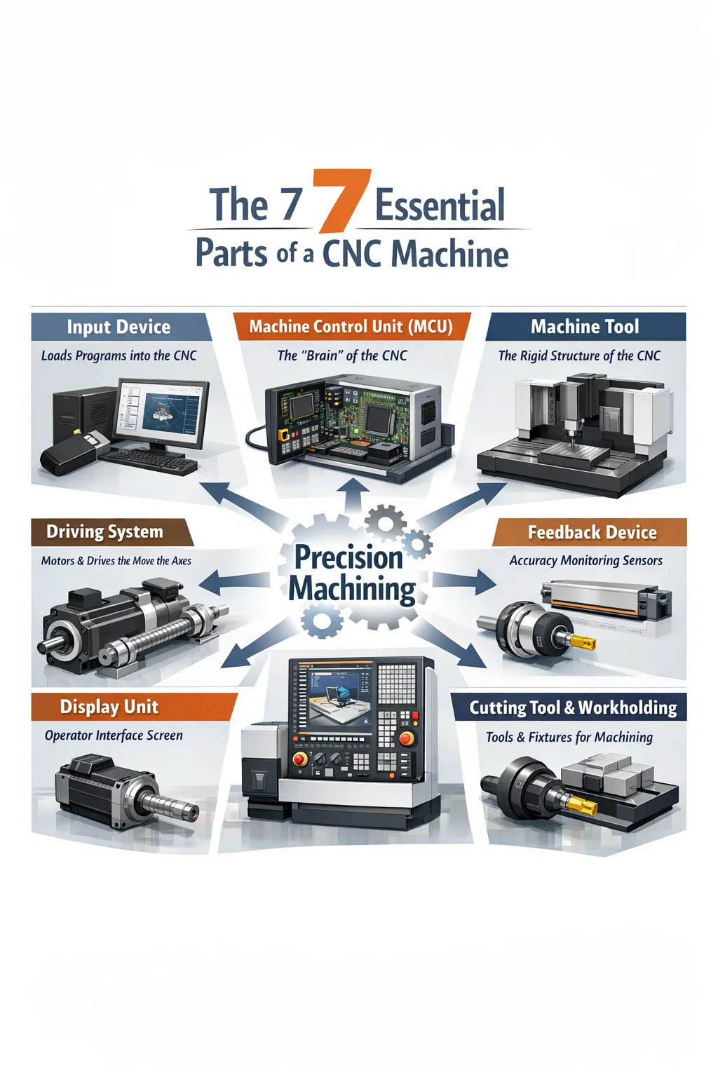
A CNC machine is made up of 7 major parts: the input device, machine control unit (MCU), machine tool, driving system, feedback device, display unit, and the cutting tool or workholding system. Each of these components plays a distinct role in converting digital instructions into precise physical cuts, bores, or shapes. Whether you are evaluating CNC equipment for a new production line or trying to understand why a machine is underperforming, knowing how these parts interact is the foundation of informed decision-making.
Modern CNC equipment operates on a closed-loop or open-loop control principle. In closed-loop systems, real-time feedback continuously corrects tool position. In open-loop systems, commands are sent without position verification. The difference matters enormously in practice: closed-loop CNC machines can hold tolerances as tight as ±0.001 mm, while open-loop systems are typically limited to ±0.01 mm under ideal conditions. Understanding which parts enable that precision is what separates operators who troubleshoot efficiently from those who guess.
The Input Device: Where Every Job Begins
The input device is the entry point for all machining instructions. In early CNC equipment, this was a punched tape reader. Today, input devices include USB ports, ethernet connections, direct CAD/CAM software interfaces, and even wireless data transfer systems. The operator or programmer uses this device to load G-code and M-code programs into the machine's control unit.
The quality and compatibility of the input device affects workflow speed significantly. A machine that accepts direct imports from software like Mastercam, Fusion 360, or SolidCAM eliminates manual code entry and reduces transcription errors. In high-mix, low-volume environments, the speed of program loading can be as operationally important as the cutting speed itself. Some facilities report reducing setup time by up to 35% simply by upgrading their CNC equipment to support direct network-based program transfer.
Input devices also store program libraries. Advanced CNC equipment may hold hundreds of part programs in internal memory, allowing operators to switch between jobs without re-uploading files. This is particularly valuable in job shops where the same part families are run repeatedly across different shifts.
The Machine Control Unit (MCU): The Brain of CNC Equipment
The machine control unit is the central processing component of any CNC machine. It reads the input program, interprets the coded instructions, and outputs electrical signals to the driving system. The MCU is what transforms a text file full of coordinates into synchronized physical motion across multiple axes simultaneously.
Inside a typical MCU, you will find a microprocessor, memory modules, interpolators, and input/output interfaces. The interpolator is especially important — it calculates the precise path the tool must follow between two points, whether that path is linear, circular, or helical. Without accurate interpolation, circular pockets would not be round and angled surfaces would be stepped rather than smooth.
Key Functions of the MCU
- Reading and decoding part programs (G-code, M-code)
- Controlling axis motion through interpolation
- Managing spindle speed and feed rate overrides
- Processing feedback signals from encoders and sensors
- Executing tool change commands and coolant control
- Monitoring safety interlocks and fault conditions
Major CNC equipment brands — Fanuc, Siemens, Mitsubishi, Heidenhain — differentiate themselves heavily at the MCU level. Fanuc's 0i-MF series, for example, supports 5-axis simultaneous control and nano-level interpolation, which is why it dominates aerospace and medical part manufacturing. Choosing the right MCU for your CNC equipment application is not a minor decision; it defines what geometries the machine can produce and how fast it can cycle.
The Machine Tool: The Structural Body That Holds Everything Together
The machine tool refers to the physical mechanical structure — the bed, column, saddle, table, and headstock — that supports all cutting operations. This is the frame of the CNC equipment, and its rigidity directly determines how well the machine can resist cutting forces without deflecting. Deflection, even in the range of a few microns, translates directly into dimensional error on the finished part.
High-quality CNC equipment manufacturers use cast iron or polymer concrete (also called Granitan or mineral casting) for machine bases. Cast iron dampens vibration effectively and has been the industry standard for decades. Polymer concrete, used in precision grinding and high-speed machining centers, offers 6 to 10 times greater vibration damping compared to cast iron, which is why you find it in Swiss-type lathes and tool grinding machines where surface finish requirements are extreme.
The guideways — either box ways or linear rails — are part of the machine tool structure. Box ways handle heavy interrupted cuts well and are common on large turning centers. Linear guideways allow faster traverse speeds and are standard on machining centers where rapid positioning matters more than brute cutting force. Many modern CNC equipment configurations combine both: box ways on the Z-axis for rigidity, linear rails on X and Y for speed.
Machine Tool Configuration Types
| Configuration | Typical Application | Key Structural Advantage |
|---|---|---|
| Vertical Machining Center (VMC) | Prismatic parts, molds, plates | Gravity-assisted chip evacuation |
| Horizontal Machining Center (HMC) | Complex multi-sided parts | 4th axis pallet rotation, better chip fall |
| CNC Lathe / Turning Center | Rotational parts, shafts, fittings | Slant-bed rigidity for heavy OD turning |
| Gantry / Bridge Mill | Large aerospace or mold components | Massive workpiece capacity, high rigidity |
The Driving System: Converting Electrical Signals Into Precise Motion
The driving system consists of servo motors, stepper motors, amplifiers, and the mechanical transmission components — ballscrews, rack-and-pinion systems, or linear motors — that move the machine's axes. This system receives low-power command signals from the MCU and converts them into high-torque, precisely controlled mechanical movement.
Servo motor-based driving systems dominate in professional CNC equipment because they provide closed-loop position control. A servo motor knows exactly where it is at all times because it is paired with a rotary encoder or linear scale. Stepper motors, used in lower-cost or hobby-grade CNC equipment, move in discrete steps and can lose position if overloaded — a problem known as step loss that does not occur with servos.
Ballscrews are the most common transmission component in CNC machining centers. A precision ground C3-class ballscrew can achieve positional accuracy of ±0.003 mm per 300 mm of travel. Rolled ballscrews, which are less expensive, typically deliver ±0.05 mm over the same distance — acceptable for general work but not for tight-tolerance aerospace or medical applications. Some ultra-high-speed CNC equipment now uses linear motor drives, which eliminate the ballscrew entirely and can reach rapid traverse speeds exceeding 120 m/min.
Servo vs. Stepper in CNC Equipment: Key Differences
- Servo motors: Closed-loop, real-time error correction, suitable for high-speed and high-precision CNC equipment
- Stepper motors: Open-loop, lower cost, risk of step loss under load, used in entry-level CNC routers and plasma tables
- Linear motors: No mechanical transmission, extremely fast response, used in high-speed die-sinking EDM and high-frequency milling
The Feedback Device: Closing the Loop on Accuracy
The feedback device measures actual machine position and reports it back to the MCU so that any deviation from the commanded position can be corrected in real time. Without a feedback device, the CNC equipment is operating blind — it sends commands and hopes the mechanics executed them exactly. With feedback, the system can detect and compensate for ballscrew wear, thermal expansion, and load-induced deflection.
Rotary encoders are the most common feedback device in CNC turning centers and machining centers. They mount on the servo motor shaft and measure rotational position. Linear scales, mounted directly on the machine's axes, provide even higher accuracy because they measure actual table position rather than inferring it from motor rotation — eliminating any error introduced by ballscrew backlash or wear. High-end CNC equipment in mold-making and optical component manufacturing uses linear scales with resolutions of 0.0001 mm (0.1 microns).
Temperature compensation is another function handled by the feedback system in premium CNC equipment. As a machine warms up during operation, thermal expansion can shift the spindle position by several microns. Machines equipped with thermal sensors and compensation algorithms — like Mazak's Thermal Shield or DMG Mori's CELOS Active Chatter Control — continuously adjust axis offsets to maintain dimensional stability across long production runs.
The Display Unit: The Operator's Window Into the Machine
The display unit, commonly called the Human-Machine Interface (HMI) or operator panel, is where the operator monitors machine status, edits programs, sets tool offsets, and responds to alarms. In older CNC equipment, this was a small monochrome screen with a physical keyboard. Modern CNC equipment features large color touchscreens — often 15 to 21 inches — with graphical simulation, 3D tool path preview, and conversational programming capability.
The usability of the display unit directly affects how quickly operators can set up jobs and respond to problems. A well-designed HMI reduces the cognitive load on the operator, especially during multi-step setups involving tool changes, work offsets, and fixture alignment. Conversational interfaces, like Mazak's MAZATROL or Okuma's OSP, allow operators to program parts using geometry inputs rather than raw G-code — significantly reducing programming time for prismatic parts and turning operations.
Networked display units on IIoT-connected CNC equipment can push real-time data to MES (Manufacturing Execution Systems), enabling remote monitoring of spindle load, tool life, cycle count, and alarm history. Facilities running connected CNC equipment report 15 to 25% improvements in OEE (Overall Equipment Effectiveness) by using this data to eliminate unplanned downtime and optimize preventive maintenance schedules.
The Cutting Tool and Workholding System: Where Metal Actually Gets Removed
The cutting tool and workholding system represent the final interface between the CNC equipment and the raw material. No matter how accurate the MCU, how rigid the machine tool, or how precise the feedback system, a worn cutting tool or improperly clamped workpiece will produce scrap. These components are often underappreciated in discussions of CNC machine architecture, but they are the point at which all other system performance is either realized or wasted.
Cutting tools for CNC equipment are typically carbide inserts or solid carbide end mills, drills, and reamers. Coatings — TiN, TiAlN, DLC, and AlCrN — dramatically extend tool life and enable higher cutting speeds. A TiAlN-coated carbide insert can run at cutting speeds 40 to 60% faster than an uncoated equivalent when machining hardened steels, directly reducing cycle time and cost per part.
Workholding on CNC equipment includes vises, chucks, collets, fixture plates, and hydraulic or pneumatic clamping systems. The choice of workholding affects setup time, part repeatability, and how many operations can be completed in a single setup. Zero-point clamping systems — such as those from Schunk, Erowa, or AMF — allow pallets to be pre-loaded offline and snapped onto the machine in under 30 seconds with repeatability of less than 0.005 mm, making them standard on automated CNC equipment cells.
Common Cutting Tool Types Used in CNC Equipment
| Tool Type | CNC Equipment Application | Typical Material |
|---|---|---|
| Carbide Insert | Turning, boring, milling | Steel, cast iron, stainless |
| Solid Carbide End Mill | Contouring, pocketing, slotting | Aluminum, titanium, hardened steel |
| Twist Drill | Hole-making in machining centers | All common engineering materials |
| CBN Insert | Hard turning (HRC 45–65) | Hardened steel, bearing races |
| PCD Tool | High-speed aluminum finishing | Non-ferrous metals, composites |
How All 7 Parts Work Together in Practice
Understanding each part in isolation is useful, but the real value comes from seeing how they interact during a live machining cycle. When an operator loads a program through the input device and presses cycle start, the MCU begins decoding instructions. It commands the driving system to rapid the axes to the starting position — the feedback device confirms arrival. The spindle accelerates to the programmed RPM, the coolant activates via an M-code signal, and the first cut begins.
During the cut, the feedback device continuously samples axis position — often at rates of 2,000 to 8,000 times per second in modern servo systems. If the cutting force deflects the table slightly, the servo amplifier commands a corrective input. The display unit shows the operator real-time spindle load, feed rate, and axis position. If tool wear increases cutting force beyond a threshold, some CNC equipment will automatically reduce feed rate to protect the part and the spindle.
This continuous loop — command, execute, measure, correct — is what makes CNC equipment so much more repeatable than manual machining. A skilled manual machinist might hold ±0.05 mm on a good day. A properly maintained CNC machining center with quality tooling and workholding holds ±0.005 mm routinely, and precision versions hold tighter still. That tenfold improvement in repeatability is the direct result of all 7 parts functioning correctly together.
What Happens When One Part Fails or Degrades
Because all 7 parts are interdependent, a problem in one propagates through the system. Diagnosing CNC equipment failures accurately requires knowing which part is the likely source of the symptom being observed.
- Dimensional drift over a production run: Often points to the feedback device (worn encoder, dirty linear scale) or thermal effects in the driving system (ballscrew expansion).
- Poor surface finish with no change in program: Usually tool wear (cutting tool system) or spindle bearing degradation (machine tool structure).
- Axis following error alarms: Typically the driving system — servo amplifier fault, motor overheating, or ballscrew binding.
- Program not loading or executing incorrectly: Input device failure, MCU memory corruption, or software compatibility issue.
- Chatter marks on part surface: Machine tool rigidity problem, worn spindle bearings, or tool stickout too long in the workholding/cutting tool system.
Structured troubleshooting that maps symptoms to specific CNC equipment subsystems reduces diagnostic time dramatically. Shops that train operators to think in terms of the 7 major parts typically resolve machine issues in 30 to 50% less time compared to those that call for service without any prior fault isolation.
Evaluating CNC Equipment Purchases Based on the 7 Major Parts
When comparing CNC equipment from different manufacturers or at different price points, using the 7-part framework gives you a structured evaluation method. Rather than comparing spindle horsepower alone — which is what most sales brochures lead with — you can assess each subsystem against your specific production requirements.
For example, a facility machining titanium aerospace components needs a rigid machine tool (box ways, large spindle taper), a high-performance MCU (5-axis capable, look-ahead buffering), a fully closed-loop driving system with linear scales, and high-pressure through-spindle coolant in the cutting tool system. A shop making aluminum enclosures for electronics needs high rapid traverse speeds, a fast tool changer, and a conversational display unit for easy programming — the requirements are completely different.
Price alone is a poor guide when selecting CNC equipment. A machine priced at $150,000 with a premium MCU, linear scale feedback, and precision ground ballscrews will outperform a $200,000 machine with a budget control and rolled screws for applications requiring consistent tolerances below ±0.01 mm. Evaluating each of the 7 parts systematically against your part tolerance requirements, material, and production volume will consistently lead to better purchasing decisions than comparing spec sheets at the headline level.
PREV:What Tooling Is Used in Vertical Milling? Complete Guide
NEXT:Cutters Used on Vertical Milling Machines: Complete Guide
NEXT:Cutters Used on Vertical Milling Machines: Complete Guide
Interested in cooperation or have questions?
News
-
-
What Is a CNC Machine? A Complete Answer A CNC machine — short for Computer Numerical Control machine — is a piece of automated manufacturing equipment that uses pre-programmed computer software to control the movement of cutti...
READ MORE -
CNC Equipment Guide What Direction Is the Z Axis on a CNC Machine? On virtually every CNC machine, the Z axis runs perpendicular to the work surface — pointing straight up and down relative to the table. Positive Z moves the spi...
READ MORE -
What Manufacturing Design Actually Means Manufacturing design is the stage of product development where a concept is converted into a buildable specification — a set of drawings, tolerances, material callouts, and process notes t...
READ MORE
Related Products


-
Factory Address
Zhaxi Township Industrial Park, Nantong City, Jiangsu Province, China (west of Huaneng Power Plant)
-
Phone
+86-13615235768
+86-15950816906
-
Fax
+86-513-85632766
-
Email
pan.director@sunwayer.com
Stay Connected
lf you can't find the answer you're looking for, chat with our friendly team.
Stay Connected
Copyright © Nantong Sunway Science and Technology Development Co., Ltd. All Rights Reserved.
China CNC Equipment Manufacturers
Custom CNC Equipment Factory
