


 русский
 Español
Heat treatment is a controlled thermal process that changes the mechanical properties of metal by heating it to a specific temperature, holding it there, and then cooling it at a rate chosen to produce a desired internal structur...
READ MORE
What Is CNC Programming? Complete Guide + Gantry Milling
Content
- 1 What Is CNC Programming?
- 2 How CNC Programming Works: From Drawing to Finished Part
- 3 Manual Programming vs CAM-Generated Programming
- 4 Core G-code and M-code Commands Every Programmer Should Know
- 5 Anatomy of a CNC Program: What Each Section Actually Does
- 6 Canned Cycles and Subprograms: Writing Less Code That Does More
- 7 Feeds and Speeds: The Math Behind Every CNC Program
- 8 CNC Programming for Large-Format Work: The Role of a CNC Gantry Milling Machine
- 9 Coordinate Systems and Work Offsets Explained
- 10 Post-Processors: Why the Same Toolpath Produces Different Code
- 11 Simulation, Verification, and First-Article Inspection
- 12 Common CNC Programming Mistakes and How to Avoid Them
- 13 Software Tools Used in Modern CNC Programming
- 14 Quick Glossary of CNC Programming Terms
- 15 Skills and Career Path for a CNC Programmer
- 16 Where CNC Programming Is Heading
- 17 Frequently Asked Questions About CNC Programming
- 17.1 Is CNC programming hard to learn?
- 17.2 Do I need to know G-code if I use CAM software?
- 17.3 What is the difference between 3-axis and 5-axis CNC programming?
- 17.4 Can the same CNC program run on different machines?
- 17.5 Why do gantry-style machines need different programming considerations than standard mills?
- 17.6 What causes most CNC programming errors on the shop floor?
- 17.7 How long does it typically take to write a CNC program?
- 17.8 What is a post-processor and why does it matter?
- 17.9 Can a CNC program run different tools automatically without operator input?
- 17.10 What is the difference between absolute and incremental positioning?
- 17.11 Why do some CNC programs include a dwell command after drilling?
- 17.12 Is it necessary to learn multiple CAM software packages?
What Is CNC Programming?
CNC programming is the process of writing a set of coded instructions, most commonly in G-code and M-code, that tell a computer numerical control machine exactly how a cutting tool should move to turn raw material into a finished part. The program controls every axis position, spindle speed, feed rate, tool change, and coolant command needed to complete a job without a machinist manually turning handwheels. Once loaded into the machine controller, the program runs the same way every single time, which is why CNC programming is the foundation of repeatable, high-precision manufacturing across aerospace, automotive, mold making, and heavy equipment industries.
In practice, CNC programming covers two connected activities: writing or generating the toolpath code, and verifying that the code will produce the correct part without crashing the tool, the fixture, or the machine spindle. A programmer may write code directly by hand for simple parts, or use CAM software to generate thousands of lines of code automatically for complex three-dimensional geometry, such as the parts produced on a large-format CNC Gantry Milling Machine.
CNC programming did not appear overnight. Early numerical control machines in the mid-twentieth century read instructions from punched paper tape, one line at a time, with almost no room for error correction. Modern controllers replaced paper tape with digital memory, networked file transfer, and graphical simulation, but the underlying logic of the language, a sequence of coordinate moves paired with machine function commands, has stayed remarkably consistent. Understanding that logic is still the single most useful skill a programmer can build, regardless of how advanced the surrounding software becomes.
It also helps to separate CNC programming from CNC operation. An operator loads material, sets up fixtures, changes tools, and monitors the running cycle. A programmer decides what that cycle actually does. In smaller shops, one person often wears both hats, moving between the controller keypad and a CAM workstation throughout the day. In larger production environments, programming is usually a dedicated office role, with finished programs handed off to operators on the floor along with a setup sheet describing fixtures, tool numbers, and offsets.
How CNC Programming Works: From Drawing to Finished Part
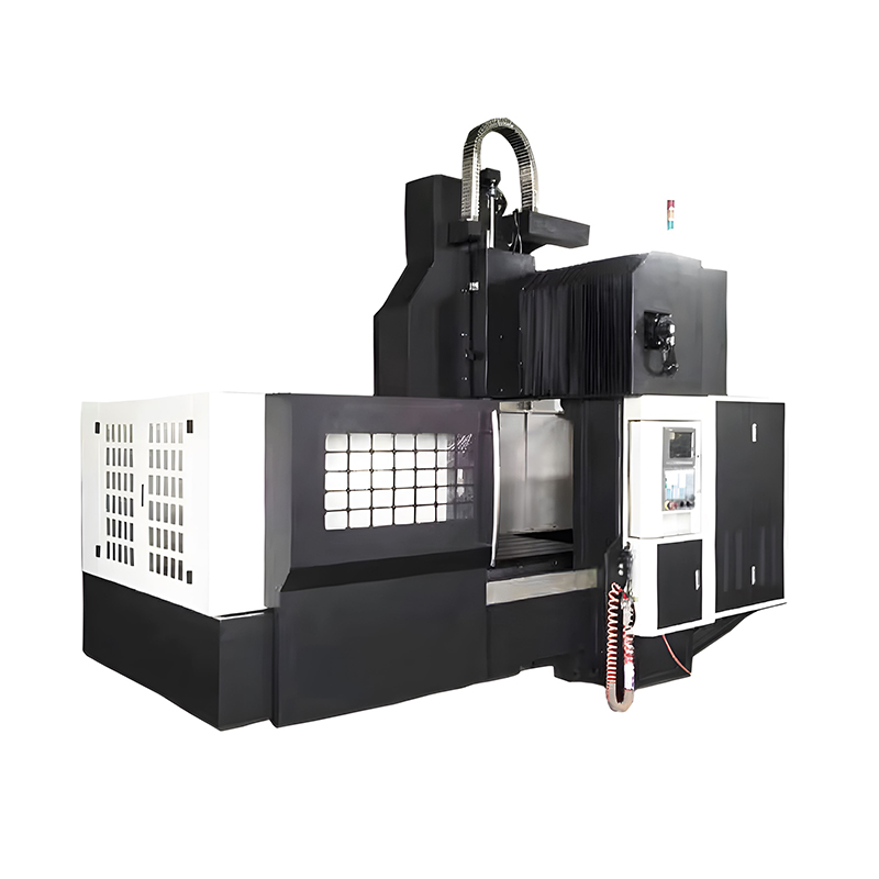
A CNC program does not appear out of nothing. It follows a fairly consistent workflow across shops, whether the target machine is a small benchtop mill or a full-size CNC Gantry Milling Machine spanning several meters of travel.
- Part geometry is created or imported in CAD software as a 2D drawing or 3D solid model.
- The programmer selects stock material, work-holding method, and the machine that will run the job.
- Toolpaths are defined, deciding which cutting tool removes which section of material and in what order.
- CAM software converts the toolpaths into G-code through a post-processor matched to the specific machine controller.
- The code is simulated or dry-run to check for collisions, over-travel, or incorrect tool lengths.
- The program is loaded onto the machine, work offsets are set, and the first part is cut and inspected.
- The first article is measured against the drawing, and any offset or toolpath adjustments are recorded before full production begins.
On large gantry-style equipment this last step matters more than it does on a small mill, because a CNC Gantry Milling Machine often carries a heavier spindle head across a wide bridge structure, and even a small programming error can translate into a large, costly movement across the table before an operator can react. Many shops build a standing checklist around this stage, covering fixture torque, tool length verification, and a single-block run of the first few lines of code before letting the cycle run at full speed.
Programming time is rarely spent evenly across these steps. On a straightforward bracket or plate, most of the time goes into CAD cleanup and toolpath selection, with G-code generation taking only a few seconds. On a large mold base run on a gantry machine, simulation and verification can consume more hours than the actual toolpath creation, simply because the cost of an undetected error scales with the size and value of the material being cut.
Manual Programming vs CAM-Generated Programming
Manual G-code Writing
Manual programming means a person types G-code and M-code line by line, usually directly at the machine controller or in a plain text editor. This method is fast and practical for simple geometry, such as drilling a bolt pattern, facing a block, or cutting a straight slot. It gives the programmer full control over every move and keeps program size small, but it becomes impractical once contoured surfaces, curved pockets, or multi-axis operations are involved.
Manual programming also remains valuable as a troubleshooting skill. When a CAM-generated program produces an unexpected result, being able to read the raw code line by line and understand exactly what each block is instructing the machine to do is often the fastest way to find the problem, rather than returning to the CAM software and regenerating the entire toolpath from scratch.
CAM-Generated Programming
Computer-Aided Manufacturing software builds toolpaths visually from a 3D model and then automatically writes the corresponding G-code. This is standard practice for parts with free-form surfaces, deep 3D contours, or multiple tool changes, and it is the only realistic way to program the long, continuous toolpaths run on a CNC Gantry Milling Machine when milling large molds, marine components, or structural panels. CAM software also allows simulation of the entire cut before any material is touched, which reduces scrap on expensive stock.
Within CAM software itself, programmers usually choose between several toolpath strategies depending on the surface being cut. Roughing strategies remove bulk material quickly with less regard for surface finish, while finishing strategies use smaller stepover distances and slower feed rates to leave a clean, accurate surface. Rest machining strategies target only the material left behind by a larger tool in an earlier pass, which keeps cycle time down by avoiding redundant cutting motion.
Hybrid Programming in Real Shops
Most experienced programmers use both methods together rather than treating them as an either-or choice. A common pattern is to generate the bulk of a program in CAM software, then manually edit specific blocks, such as adding a dwell command, adjusting a single feed rate, or inserting a custom subprogram call, once the base toolpath has been verified.
| Factor | Manual Programming | CAM Programming |
|---|---|---|
| Best suited to | Simple, prismatic parts | Complex, contoured, or large-scale parts |
| Setup time | Very short | Longer, but reusable across similar parts |
| Collision checking | Manual review only | Built-in simulation |
| Editing after generation | Direct and immediate | Usually regenerated from the source toolpath |
| Typical machine type | Benchtop mill, lathe | Gantry mill, 5-axis machining center |
Core G-code and M-code Commands Every Programmer Should Know
G-code and M-code together form the language a CNC controller reads. G-codes handle geometric moves, while M-codes handle machine-level functions such as turning on coolant or stopping the spindle. The command set is standardized in principle under ISO 6983, though most controller manufacturers add their own extensions on top of the base command set.
| Code | Function | Typical Use |
|---|---|---|
| G00 | Rapid positioning | Moving the tool quickly between cuts |
| G01 | Linear interpolation | Straight-line cutting at a set feed rate |
| G02 / G03 | Circular interpolation | Cutting arcs clockwise or counterclockwise |
| G17 / G18 / G19 | Plane selection | Choosing the XY, XZ, or YZ plane for arc moves |
| G20 / G21 | Unit selection | Switching between inch and metric programming |
| G40 / G41 / G42 | Cutter compensation | Offsetting the toolpath left or right of programmed geometry |
| G43 | Tool length compensation | Applying the stored length offset for the active tool |
| G54 to G59 | Work coordinate offsets | Setting the part zero point on the table |
| G80 | Cancel canned cycle | Ending a drilling or tapping cycle before the next move |
| G81 to G89 | Canned drilling cycles | Repeating a drilling or tapping motion across multiple hole locations |
| G90 / G91 | Positioning mode | Switching between absolute and incremental coordinates |
| M00 / M01 | Program stop | Pausing the cycle for inspection or a fixture change |
| M03 / M04 / M05 | Spindle control | Starting the spindle clockwise, counterclockwise, or stopping it |
| M06 | Tool change | Swapping to the next tool in the program |
| M08 / M09 | Coolant control | Turning flood coolant on or off |
| M30 | Program end and reset | Ending the program and returning to the first line |
A programmer rarely memorizes every code available on a given controller. Instead, most shops build a working vocabulary of these commands, then reference the machine builder's programming manual for anything unusual, such as macro variables, custom probing cycles, or manufacturer-specific canned routines used in high-volume production.
Anatomy of a CNC Program: What Each Section Actually Does
Beyond individual commands, a finished CNC program is organized into recognizable sections that follow a consistent order across most controllers. Understanding this structure makes it far easier to read someone else's program or troubleshoot an existing one.
Program Header
The header identifies the program number and often includes a comment line naming the part, the material, and the programmer, purely for record-keeping. It also typically sets the unit system and safety block, canceling any leftover offsets from a previous job before the real cutting motion begins.
Tool Change Blocks
Each time the program calls a new tool, it includes a tool number, a length compensation command, and a spindle speed appropriate to that specific tool and material. On programs with a large number of tools, this section is often the longest part of the code simply due to repetition.
Cutting Motion Blocks
This is the core of the program, containing the actual G01, G02, and G03 moves that remove material. On CAM-generated code this section can run for thousands of lines on a complex 3D surface, especially when a fine stepover is used for a smooth finish pass.
Program End Block
The final lines retract the tool to a safe height, turn off the spindle and coolant, and issue an M30 command to end the cycle and reset the controller for the next run.
Canned Cycles and Subprograms: Writing Less Code That Does More
One of the most practical efficiency tools in CNC programming is the canned cycle, a single block of code that expands internally into a repeated sequence of moves. Drilling is the clearest example: instead of writing out the rapid approach, feed down, and retract for every single hole, a programmer defines the cycle once with G81 or a similar code, then lists only the X and Y coordinates for each hole location.
Subprograms extend this same idea to entire toolpath sequences rather than single cycles. A subprogram is written once, stored under its own program number, then called from the main program as many times as needed, often with different work offsets so the identical operation repeats at several locations. This approach is especially useful for parts with repeated features, such as a plate with several identical mounting bosses machined on a CNC Gantry Milling Machine across multiple work zones.
Beyond saving typing time, canned cycles and subprograms reduce the chance of a transcription error, since a mistake made once in the cycle definition is far easier to find and fix than the same mistake repeated across dozens of individually written blocks.
Feeds and Speeds: The Math Behind Every CNC Program
Every toolpath in a program is only as good as the feed rate and spindle speed paired with it. Getting this wrong does not usually stop the machine from running, but it does show up as poor surface finish, premature tool wear, or in more serious cases, a broken cutter mid-cycle.
Spindle speed is generally derived from a recommended cutting speed for the specific tool and material combination, then converted to a rotations-per-minute value based on the tool's diameter. Feed rate is then calculated from that spindle speed together with the number of cutting edges on the tool and a target chip load, which is the thickness of material each cutting edge removes per revolution.
- Harder materials generally call for slower cutting speeds and lighter chip loads to avoid excess heat at the cutting edge.
- Softer, more gummy materials often need higher chip loads to avoid the tool rubbing rather than cutting cleanly.
- Longer, more flexible tools generally require reduced feed rates compared to short, rigid tools of the same diameter, to avoid deflection.
- On large-format equipment such as a CNC Gantry Milling Machine, rigidity across a wide gantry span can vary slightly depending on tool position, which some programmers account for by adjusting feed rates near the extremes of travel.
Tool manufacturers publish starting feed and speed values for their products, and most CAM software includes built-in cutting data libraries that suggest values automatically once the material and tool are selected, though experienced programmers still adjust these figures based on the specific rigidity of the machine and fixture in use.
CNC Programming for Large-Format Work: The Role of a CNC Gantry Milling Machine
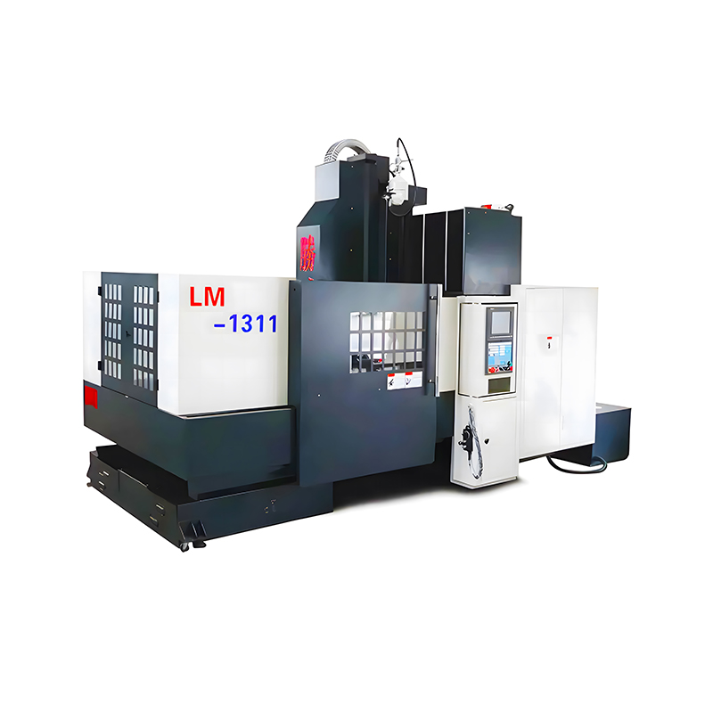
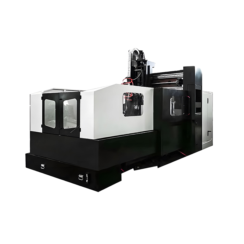
Standard vertical machining centers are built around a fixed column and a table that moves under a stationary or lightly traveling spindle head. A CNC Gantry Milling Machine takes a different structural approach: the spindle head rides on a bridge, or gantry, that spans two parallel rails on either side of a fixed table. This layout lets the machine cover very large work envelopes, often several meters in the X axis, without the table itself having to move a heavy part.
From a programming standpoint, working with a gantry machine changes a few practical habits:
- Work offsets must account for a fixed table and multiple possible fixture zones, since large parts are often clamped in more than one location across the bed.
- Rapid moves need extra caution, because the gantry head travels a longer physical distance and carries more mass than a small mill head, so a programming mistake has more energy behind it.
- Toolpath strategies favor continuous, sweeping passes over large flat or contoured surfaces, since a gantry machine is frequently used for mold bases, marine components, and structural aluminum or steel plates.
- Thermal growth across a long bridge structure is sometimes factored into tight-tolerance programs, since a large steel gantry can expand slightly over long production runs.
- Multiple parts are often fixtured side by side across the bed and programmed as a single cycle using repeated work offsets, which keeps the machine running continuously rather than stopping between individual setups.
Because a CNC Gantry Milling Machine is typically chosen for large, high-value workpieces, programmers on this equipment tend to run more simulation cycles before cutting live material than they would on a small job shop mill, simply because the cost of a mistake is proportionally higher.
Typical Industries and Applications
Gantry milling machines commonly appear in industries where the finished part or mold simply will not fit inside a standard machining center envelope. This includes shipbuilding components, large injection mold bases, wind turbine tooling, heavy equipment structural parts, and aerospace fixture plates. In each of these cases, the alternative to a gantry machine is often splitting the part into smaller sections and joining them afterward, which introduces additional tolerance stack-up and assembly work that a single-setup gantry program avoids.
Fixturing Considerations Unique to Gantry Work
Because the table on a gantry machine does not move, fixturing is planned around fixed T-slot patterns or modular clamping grids built into the bed itself. Programmers often coordinate closely with the fixturing plan before writing any toolpath, since a clamp or riser left in the wrong location can sit directly in the path of a tool that appears completely clear in the CAM simulation if the physical fixture layout was not modeled accurately.
Coordinate Systems and Work Offsets Explained
Every CNC program is built around coordinates, and understanding the difference between them prevents one of the most common beginner mistakes.
Machine Coordinate System
This is fixed to the physical machine itself, typically zeroed at a home position established by limit switches. The programmer almost never writes code directly against this system.
Work Coordinate System
This is a movable zero point that the operator sets on the actual part, using G54 through G59 or extended offset registers on larger controllers. Setting the wrong work offset is one of the leading causes of a scrapped first part, since the entire program will run correctly in relation to the wrong physical location.
Tool Length and Tool Diameter Offsets
Separate from the part coordinate system, each tool carries its own length and diameter values in the controller's offset table. The program calls a tool number, and the machine automatically compensates for that specific tool's geometry, which is what allows the same program to run correctly even after a tool is replaced with a new one of slightly different length.
Rotational and Multi-Axis Offsets
On machines with rotary axes, an additional offset accounts for the pivot point of the rotary table or head relative to the spindle. Getting this value wrong does not usually cause a problem on simple flat work, but it becomes very visible on any operation that tilts the tool, since the part will shift position slightly every time the rotary axis moves if the pivot offset is inaccurate.
Post-Processors: Why the Same Toolpath Produces Different Code
A post-processor is a translation file inside CAM software that converts a generic internal toolpath into the specific G-code dialect a particular machine controller understands. Two machines can be given the exact same CAM toolpath and still produce noticeably different code, because one controller might expect G28 for a home return while another expects a completely different syntax, or one machine might support a canned drilling cycle that another does not.
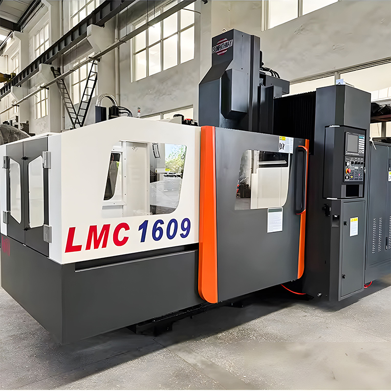
This is a frequent source of confusion for programmers moving between shops or between machine brands, and it is also the reason a program written for a small vertical mill cannot simply be copied over and run on a CNC Gantry Milling Machine without regenerating it through the correct post-processor, even if the part geometry is identical. A mismatched post-processor is one of the most common causes of an otherwise correct-looking program producing an alarm or an incorrect motion on start-up.
Simulation, Verification, and First-Article Inspection
Verification is the stage where a program is checked before it ever touches real material, and it typically happens on more than one level.
Graphical Simulation in CAM Software
Before the code leaves the office computer, CAM software can simulate the entire toolpath against a virtual stock model, highlighting gouges, excessive material left behind, or tool holder collisions with clamps and fixtures.
Machine-Side Dry Run
Many controllers support running the program with the spindle off and rapid rates reduced, allowing an operator to watch the tool trace the entire path in the air above the actual fixture, which catches real-world clearance issues that a simulation based on an idealized 3D model sometimes misses.
Single-Block Operation
For the first few cuts on a new or heavily revised program, operators frequently run in single-block mode, where the machine executes one line of code at a time and pauses, giving a chance to stop immediately if anything looks wrong before the next move begins.
First-Article Inspection
Once the first complete part comes off the machine, it is measured against the engineering drawing before the program is approved for a full production run. Any deviation found here is usually traced back to either a work offset error, a tool wear compensation issue, or occasionally a genuine mistake in the programmed geometry itself.
Common CNC Programming Mistakes and How to Avoid Them
| Mistake | Why It Happens | Prevention |
|---|---|---|
| Wrong work offset selected | Operator loads the wrong G54 to G59 register | Label fixtures clearly and confirm offset before the cycle start |
| Incorrect tool length compensation | Tool was measured incorrectly or the wrong tool number was called | Re-measure tools after any change and verify tool numbers in the program header |
| Skipping dry-run simulation | Time pressure to get a job running quickly | Always run graphical simulation or an air cut before the first real part |
| Feed and speed mismatched to material | Program reused from a different material without adjustment | Reference material-specific cutting data before finalizing the program |
| Ignoring machine travel limits | CAM post-processor not matched correctly to the machine | Verify the post-processor against the exact machine model and axis travel |
| Fixture or clamp collision | Fixture was not accurately modeled in the CAM simulation | Model clamps and risers to their real position before simulating the toolpath |
| Leftover offset from a previous job | Program header does not reset compensation and offsets | Start every program with a standardized safety block that cancels prior modes |
Software Tools Used in Modern CNC Programming
Most shops rely on a combination of tools rather than a single program, since design, toolpath generation, and simulation are often handled by different pieces of software.
- CAD software is used to build or import the part geometry that the program will follow.
- CAM software converts geometry into toolpaths and generates the final G-code through a post-processor.
- Simulation and verification software checks the program against a virtual model of the machine, table, and fixtures to catch collisions before the spindle ever turns.
- DNC transfer utilities move the finished program from an office computer to the machine controller, either over a network or through direct cable transfer on older equipment.
- Tool and cutting data libraries store recommended feeds, speeds, and holder geometry so the same tool information can be reused consistently across multiple programs.
- Program management systems track revisions, approvals, and which version of a program is currently released to the shop floor, which becomes important once a part has gone through several rounds of adjustment.
On a large CNC Gantry Milling Machine, the simulation step carries extra weight, since verifying gantry clearance over tall fixtures or thick stock is far cheaper to catch on screen than on the shop floor.
Quick Glossary of CNC Programming Terms
| Term | Meaning |
|---|---|
| Block | A single line of a CNC program |
| Chip load | The thickness of material removed by each cutting edge per revolution |
| Stepover | The distance between adjacent passes of a toolpath |
| Rest machining | Cutting only the material left behind by a previous, larger tool |
| Dwell | A programmed pause with no motion, often used to clear a drilled hole |
| Post-processor | The CAM translation file that outputs code matched to a specific controller |
Skills and Career Path for a CNC Programmer
Most CNC programmers start on the machine floor as an operator or setup technician, building an intuitive feel for how a program actually behaves in metal before moving into a dedicated programming role. From there, the skill set typically grows in this order:
- Reading engineering drawings and interpreting tolerances, surface finish callouts, and geometric dimensioning symbols.
- Understanding basic machining principles, including cutting speeds, feeds, tool wear, and material behavior.
- Writing and editing G-code by hand for simple operations.
- Learning CAM software to handle contoured, multi-axis, or high-volume work efficiently.
- Gaining experience across different machine platforms, from small vertical mills to a full-size CNC Gantry Milling Machine, since each machine layout has its own quirks in offsets, travel limits, and post-processing.
- Developing fixture and work-holding awareness, since a program is only as good as the physical setup it assumes.
Programmers who work across multiple machine types tend to become the most valuable in a shop, because they can move a job between a small mill and a large gantry machine depending on part size without needing to relearn the fundamentals each time. Communication skills also matter more than many newcomers expect, since a programmer regularly needs to explain setup requirements clearly to operators who did not write the program themselves.
Where CNC Programming Is Heading
Several trends are gradually reshaping day-to-day CNC programming work without replacing the underlying G-code foundation. Adaptive toolpath strategies now adjust feed rate in real time based on measured cutting load, keeping tool engagement consistent even as pocket geometry changes across a single operation. In-process probing has become common on both small mills and large gantry machines, allowing a program to measure a part or fixture position automatically and adjust its own offsets before cutting begins, which reduces the manual setup burden described earlier in this article.
Cloud-based CAM platforms and shared program libraries are also making it easier for a programmer to hand off work between office and shop floor, or between two shops entirely, without losing track of which version of a program is current. None of these developments change the fundamental logic behind CNC programming described at the start of this guide, but they do continue to reduce the manual, repetitive parts of the job, freeing programmers to spend more time on toolpath strategy and less on transcription and setup verification.
Frequently Asked Questions About CNC Programming
Is CNC programming hard to learn?
The basics of reading and writing simple G-code can be picked up in a matter of weeks with hands-on practice, but developing the judgment to program complex parts efficiently, choose the right toolpath strategy, and troubleshoot problems on the machine takes considerably longer, often measured in years of shop experience.
Do I need to know G-code if I use CAM software?
Yes. CAM software generates the code automatically, but a programmer still needs to understand what the generated code is doing in order to catch errors, edit a program by hand when needed, and troubleshoot problems at the machine controller.
What is the difference between 3-axis and 5-axis CNC programming?
3-axis programming moves the tool along X, Y, and Z only, which suits flat or moderately contoured parts. 5-axis programming adds two rotational axes, allowing the tool to approach a surface from nearly any angle, which is necessary for deep pockets, undercuts, and complex curved geometry that a 3-axis setup cannot reach in a single operation.
Can the same CNC program run on different machines?
Not directly. Each machine controller has its own specific command set and travel limits, so a program must be regenerated through the correct post-processor for the target machine, whether that machine is a small mill or a large CNC Gantry Milling Machine.
Why do gantry-style machines need different programming considerations than standard mills?
A gantry machine covers a larger work envelope and typically carries a heavier spindle head across a bridge structure, so programmers pay closer attention to rapid move paths, fixture clearance, and work offset accuracy across a wider table area.
What causes most CNC programming errors on the shop floor?
The majority of real-world errors trace back to incorrect work offsets, mismatched tool numbers, or skipping the simulation step before running the first live part, rather than errors in the underlying toolpath logic itself.
How long does it typically take to write a CNC program?
A simple prismatic part with a few holes and pockets can be programmed in well under an hour using CAM software. A complex mold surface or a large multi-fixture part on a gantry machine can take anywhere from several hours to a few days, depending on toolpath complexity and the number of simulation passes required.
What is a post-processor and why does it matter?
A post-processor is the file inside CAM software that translates a generic toolpath into the exact code dialect a specific machine controller expects. Using the wrong post-processor is a common cause of programs that appear correct in simulation but produce unexpected results, or trigger alarms, once loaded onto the actual machine.
Can a CNC program run different tools automatically without operator input?
Yes, on machines fitted with an automatic tool changer, a single M06 command in the program swaps tools without any manual intervention, as long as the correct tools are already loaded into the magazine before the cycle starts.
What is the difference between absolute and incremental positioning?
Absolute positioning, set with G90, defines every coordinate relative to the fixed part zero point. Incremental positioning, set with G91, defines each move relative to the tool's current position instead, which is occasionally useful for repeated patterns but is used far less often than absolute positioning in most modern programs.
Why do some CNC programs include a dwell command after drilling?
A short dwell pauses the tool at the bottom of a hole with no motion, which allows the cutting edge to fully clear chips and produce a cleaner hole bottom, particularly on materials that tend to leave a small nub if the tool retracts immediately.
Is it necessary to learn multiple CAM software packages?
Not necessarily, since the underlying toolpath concepts, roughing, finishing, and rest machining, are shared across nearly all CAM platforms. Learning one package thoroughly makes picking up a second one considerably faster, because the core logic transfers even when the menu layout and terminology differ.
PREV:What Does CNC Stand For? Understanding CNC Equipment
NEXT:What Is a CNC Wire Cut Machine? Working Principle & Uses
NEXT:What Is a CNC Wire Cut Machine? Working Principle & Uses
Interested in cooperation or have questions?
News
-
-
An EDM machine, also called an electrical discharge machining machine, uses controlled sparks to erode electrically conductive metal without direct contact between the tool and the workpiece. The workpiece is submerged in a diele...
READ MORE -
Cutting Tools Are Used to Convert Raw Material into Functional Parts Cutting tools are the hardened, wear-resistant elements that shear away unwanted material from a workpiece to create a finished component. They are applied in e...
READ MORE -
A CNC machine can cut, drill, mill, turn, burn, and shape almost any conductive or composite material with an accuracy that manual machines rarely match. The real question is not what a CNC machine can do in theory, but what a sp...
READ MORE
Related Products

-
Factory Address
Zhaxi Township Industrial Park, Nantong City, Jiangsu Province, China (west of Huaneng Power Plant)
-
Phone
+86-13615235768
+86-15950816906
-
Fax
+86-513-85632766
-
Email
pan.director@sunwayer.com
Stay Connected
lf you can't find the answer you're looking for, chat with our friendly team.
Stay Connected
Copyright © Nantong Sunway Science and Technology Development Co., Ltd. All Rights Reserved.
China CNC Equipment Manufacturers
Custom CNC Equipment Factory
