


 русский
 Español

An endmill is a rotating cutting tool that removes material with cutting edges on both its cylindrical side and its tip. It is gripped in the spindle through a collet, a hydraulic holder or a shrink-fit holder, spins on its own a...
READ MORE
What Is an Endmill? Definition, Types, Coatings and CNC Milling Basics
Content
- 1 The Anatomy of an Endmill: Shank, Flutes, Helix and Cutting Edges
- 2 Endmill vs Drill Bit vs Other Cutters: The Difference That Matters
- 3 The Main Endmill Types and What Each One Is For
- 4 Flutes, Helix Angle and Coating: How to Read a Tool Label
- 5 Speeds, Feeds and Practical Starting Numbers
- 6 How the Endmill Fits Into a Real Machining Sequence
- 7 Where Milling Stops Working: The EDM Handoff
- 8 Endmills in Superalloys and Hardened Tool Steel
- 9 What Goes Wrong: Common Endmill Problems and Their Causes
- 10 Buying Considerations: Tolerances, Repeatability and Cost per Part
- 11 Frequently Asked Questions About Endmills
- 11.1 What is an endmill in one sentence?
- 11.2 Can an endmill be used as a drill?
- 11.3 How many flutes should I choose?
- 11.4 What is the difference between a flat and a ball nose endmill?
- 11.5 Why does my endmill wear out so quickly?
- 11.6 Can an endmill cut hardened steel?
- 11.7 Does an endmill cut on the side or the end?
- 11.8 Is a roughing endmill worth it on a small machine?
- 11.9 What causes an endmill to pull out of the holder?
- 11.10 How much overhang is acceptable?
- 12 The Short Version
An endmill is a rotating cutting tool that removes material with cutting edges on both its cylindrical side and its tip. It is gripped in the spindle through a collet, a hydraulic holder or a shrink-fit holder, spins on its own axis, and is fed in X, Y and Z so it can cut in almost any direction the machine permits. A drill can travel only along its own axis, so a drill makes round holes and an endmill makes slots, shoulders, pockets, profiles and three-dimensional surfaces.
That is the short answer. It is enough to pass a quiz, but it is not enough to buy a tool or run a job. The word endmill covers a family that stretches from a 0.5 mm micro cutter trimming a watch plate to a 160 mm shell mill peeling several millimetres of stock off a welded frame. Two tools carrying the same name can differ in substrate, coating, helix angle, flute count, corner geometry and shank tolerance, and those differences decide whether the tool survives twenty minutes or four hours.
The pages below cover what an endmill actually is, how it differs from a drill bit, which types exist, how to read a tool label, what speeds and feeds look like on the shop floor, and where milling hands the job over to electrical discharge machining.
The Anatomy of an Endmill: Shank, Flutes, Helix and Cutting Edges
Every endmill, whether it costs eight dollars or eight hundred, is built from the same handful of features. Understanding them turns a catalogue page into something you can actually specify from.
- Shank. Cylindrical, cylindrical with a Weldon flat for a side-lock holder, or a tapered interface for high-speed spindles. The shank transmits torque and largely sets the runout the cutting edges will see.
- Flutes. The helical grooves that carry chips away. Flute count governs chip room, core strength and the feed rate you can reach: more teeth means a higher table feed, but less space for the chip to escape.
- Helix angle. The twist of the cutting edge. Around 30 degrees is a general-purpose compromise, 38 to 45 degrees shears the chip faster and suits steel and aluminium, and a shallow 15 to 20 degrees helps on brass and thin-walled parts.
- End cutting edges. The teeth on the tip. A centre-cutting endmill has them and can plunge or ramp; a non-centre-cutting tool does not and will burn if you feed it straight down.
- Corner geometry. Square, small radius or full ball. A corner radius is often the single biggest lever on tool life, because a perfectly sharp corner concentrates stress and chips first.
- Coating and edge preparation. What the carbide is wrapped in and how the micro-geometry has been honed. Both change how the tool behaves far more than the headline price does.
Runout deserves its own line. Mount the tool, bring a dial indicator onto a cutting edge and turn the spindle by hand. Under 0.01 mm total indicated runout is a sensible target for a finishing tool. At 0.02 mm or more, one tooth takes most of the load, overheats and fails while the other teeth still look brand new. That measurement costs two minutes and is one of the cheapest tool-life improvements in any shop.
Endmill vs Drill Bit vs Other Cutters: The Difference That Matters
The practical distinction between an endmill and a drill bit is direction of travel. A drill is designed for one plunge along its axis. An endmill is designed to be pushed sideways, which is why it can open a slot, step down a shoulder, interpolate a bore or sweep a contoured surface. The table below summarises the tools people most often confuse.
| Tool | Primary motion | Typical job | Cuts sideways |
|---|---|---|---|
| Drill bit | Axial only | Round holes | No |
| Flat endmill | Axial and lateral | Slots, pockets, shoulders | Yes |
| Ball nose endmill | Multi-axis contouring | 3D surfaces and radii | Yes |
| Bull nose endmill | Axial and lateral | Roughing with a strong corner | Yes |
| Face mill | Lateral, shallow | Large flat surfaces | Shallow only |
| Reamer | Axial only | Sizing a drilled hole | No |
| Thread mill | Helical interpolation | Internal and external threads | Yes |
One consequence is often overlooked. Because an endmill is stiff in bending and weak in torsion, side loading, not spindle speed, is what usually destroys it. A drill breaks when you push too hard along its axis. An endmill breaks when you hang it too far out of the holder and then crowd it sideways.
The Main Endmill Types and What Each One Is For
Most job shops keep a fairly small working set and reach for the same few geometries again and again. Here is how that set is usually organised, and the job each tool is bought for.
- Flat or square endmill. The default. Slots, shoulders, pockets and general profiling in steel, aluminium and plastics.
- Ball nose endmill. Used for three-dimensional forms, fillets and die surfaces. It is the tool of choice whenever a radius has to be swept smoothly rather than stepped.
- Bull nose or corner radius endmill. A flat tool with a small radius at the corner. It roughs almost as efficiently as a square tool but survives far longer, especially in hardened or abrasive material.
- Roughing endmill. A serrated or corncob edge that breaks the chip into small pieces. Excellent for deep pockets in steel and for removing stock quickly on a light machine.
- Chamfer and V-bit cutters. Used for edge breaks, countersinks, engraving and mould parting lines.
- Dovetail and T-slot cutters. Undercut geometries for slides, guide rails and clamping features that cannot be reached from vertically above.
- Thread mills. Produce threads by helical interpolation, which means one tool can cut a range of diameters and a range of pitches.
- Micro endmills. Below about 1 mm in diameter, where runout, chip clearance and spindle vibration decide everything.
- Engraving and tapered cutters. Fine-detail work on electrodes, moulds and nameplates. Shops that cut a lot of graphite electrodes run dedicated machines and tools for it; the principles are covered in this guide to CNC engraving milling machines.
- High-feed endmills. A small lead angle at the tip shifts the cutting load upward, allowing very high table feeds at shallow depths of cut.
Flutes, Helix Angle and Coating: How to Read a Tool Label
Flute count sets the balance between chip room and feed rate
Two flutes leave a large gullet and are the classic choice for aluminium and other soft, gummy materials where the chip is big and must leave fast. Three flutes sit in the middle and handle aluminium, plastics and light steel work. Four flutes are the steel standard. Five, six and more flutes are for finishing, for hard materials and for high-feed strategies where the chip is thin and controlled. If you are slotting at full width, stay with fewer flutes; if you are profiling with light radial engagement, more flutes let you raise the table feed substantially.
Helix angle controls shear, chatter and lift
A steeper helix shears the material more efficiently and pushes the chip up the flute, but it also pulls the tool out of the holder and generates axial load. That is why very steep tools are usually paired with shrink-fit or hydraulic holders rather than a plain collet. Variable-helix and variable-pitch tools are deliberately irregular so that the teeth do not all hit the same frequency and chatter stays away.
Coatings decide which materials a tool can survive
Coating choice is not cosmetic. It controls heat transfer, chemical wear and how much the chip sticks to the edge. The table gives the usual pairings.
| Coating | Best suited to | Watch out for |
|---|---|---|
| Uncoated carbide | Aluminium, plastics, graphite | Short life in steel |
| TiN | General steel, low cost work | Breaks down at high temperature |
| TiAlN | Steel and stainless, dry or minimum lubrication | Not ideal for aluminium |
| AlTiN and AlCrN | Hardened steel, titanium, nickel alloys | Needs rigid setups and stable heat |
| Diamond-like carbon | Aluminium, composites, graphite | Poor on ferrous materials |
Speeds, Feeds and Practical Starting Numbers
Two formulas cover most of the arithmetic on the shop floor. Spindle speed follows surface speed: rpm equals surface speed in metres per minute multiplied by 1000, divided by pi multiplied by the tool diameter in millimetres. Table feed follows chip load: feed in millimetres per minute equals feed per tooth multiplied by the number of teeth multiplied by rpm.
A worked example makes the difference clear. A 12 mm four-flute carbide endmill cutting 6061 aluminium at a surface speed of 400 metres per minute runs at roughly 10,600 rpm. With a feed per tooth of 0.05 mm, the table feed is about 2,120 mm per minute. Halve the tool diameter and the rpm doubles, which is exactly why small tools demand fast spindles and why a slow spindle quietly caps your productivity.
| Workpiece material | Surface speed (m/min) | Notes |
|---|---|---|
| Aluminium 6061 | 300 to 600 | Flood coolant or air blast; watch chip welding |
| Brass and copper | 200 to 400 | Shallow helix helps control grab |
| Mild steel 1018 | 90 to 150 | Four flutes works well |
| Alloy steel 4140 | 70 to 120 | Reduce speed as hardness rises |
| Stainless 304 or 316 | 40 to 80 | Never dwell; work hardening is the enemy |
| Titanium Ti-6Al-4V | 25 to 60 | High coolant pressure is essential |
| Nickel alloy 718 | 15 to 40 | Expect short tool life and plan for it |
| Hardened steel 50 HRC | 30 to 70 | Use a corner radius and a stable holder |
Treat every number here as a starting point, not a rule. Rigidity, tool overhang, coolant delivery and machine condition routinely move the usable range by 30 percent in either direction. The fastest way to find your real limit is to raise the feed until the chip colour and sound change, then back off one step.
How the Endmill Fits Into a Real Machining Sequence
In production, an endmill is rarely used alone. A typical mould or precision part goes through a sequence: face the stock, rough the cavity with a large bull nose or roughing tool, semi-finish with a smaller flat tool, then finish with a ball nose on a three-axis or five-axis path. Each step trades tool strength against detail. The roughing tool needs stiffness and chip room; the finishing tool needs accuracy and a fine edge.
The machine underneath matters as much as the cutter. A three-axis vertical machining centre with a rigid frame, a temperature-stable spindle and enough rpm to run small tools at their rated surface speed is the standard home for a 12 mm carbide endmill doing pockets and profiles all day. That combination of spindle speed, structural stiffness and repeatable tool change is what turns a good cutter into predictable cycle times.
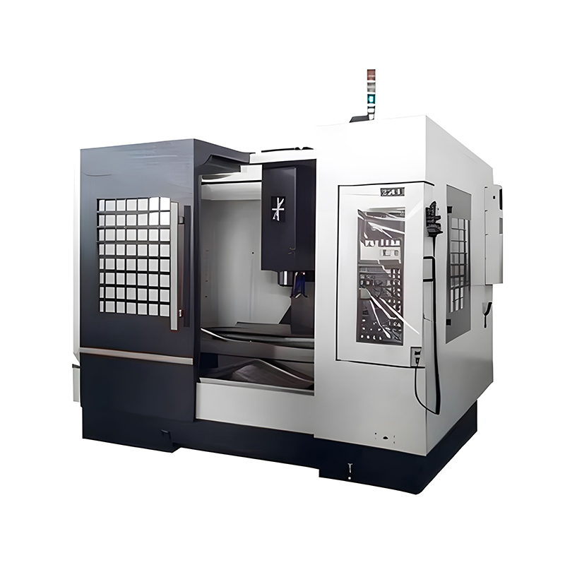 VMC850L High Speed 3 Axis CNC Vertical Machining CenterApplication scenarios and scope of application This machining center is widely used in the production of precision components, including engine parts, hydraulic fittin...View Product →
When specifying the machine, ask three questions that come directly from endmill behaviour. Can the spindle hold the rpm the tool needs at its diameter? Can the structure absorb the side load without chatter? And can the tool changer and holder repeat position closely enough that runout stays inside tolerance shift after shift?
Where Milling Stops Working: The EDM Handoff
An endmill has a hard limit. When the feature is a sharp internal corner narrower than the smallest tool you own, when the material is above roughly 60 HRC, or when the geometry is a deep rib that would need a tool so slender it snaps on contact, milling stops being economical. That is when die-sinking electrical discharge machining takes over.
The logic is simple. Milling removes the bulk quickly with a rotating cutter; EDM burns the final detail with an electrode that never touches the workpiece, so hardness stops being the deciding factor. A small three-axis CNC die-sinking machine is the usual partner for a mould shop that already owns a machining centre, because it handles the corner radii, the sharp internal edges and the hardened inserts that the endmill cannot reach. For readers who want the underlying principle, this overview of electrical discharge machining explains how the spark gap does the cutting.
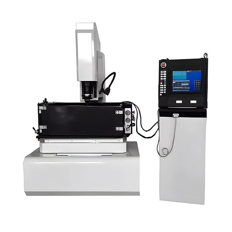 CNC-430 Small CNC Electrical Discharge Machine for Metal Mould MakingApplication scenarios and scope of application Micro-feature engraving in injection mold cavities Blind hole machining for mold cooling channels Detailed finishing on ...View Product →
Planning tip: leave 0.2 to 0.5 mm of stock on surfaces that will be finished by EDM. That lets the endmill run at a productive feed instead of creeping along a finished wall, and it gives the electrode a consistent amount of material to remove.
Endmills in Superalloys and Hardened Tool Steel
Titanium, nickel alloys and hardened tool steel behave very differently from mild steel. They conduct heat poorly, so the heat stays in the cutting edge. They work harden quickly, so a tool that rubs instead of cutting will make the next pass harder than the last. And they are abrasive, so coating breakdown is often what ends a tool's life rather than a fracture.
Practical responses include lower surface speeds, high-pressure coolant aimed at the cutting edge, climb milling wherever possible, a corner radius instead of a sharp corner, and a firm commitment to never let the tool dwell. Even so, some features in these materials are better produced by spark erosion than by a rotating cutter, particularly deep small holes and features in parts that are already heat treated. Purpose-built multiaxis EDM drilling systems exist for exactly that class of work.
 CNC Multi-axis EDM Drilling Machine SuppliersVIEW MORE XK-430 High-Speed CNC 5-Axis EDM Drilling Machine XK-430 High-Speed CNC 5-Axis EDM Drilling Machine is a precision-engineered electrical discharge mac...View Product →
Electrochemical machining goes one step further and removes material without a heat-affected zone at all, which matters on thin blades, film cooling holes and coated surfaces where a recast layer would have to be removed afterwards.
What Goes Wrong: Common Endmill Problems and Their Causes
Most endmill failures fall into a small number of patterns. Matching the symptom to the cause saves a lot of guessing.
- Chatter and wavy walls. Usually too much overhang, an unbalanced holder, a feed that is too light, or a tooth passing frequency that matches a natural frequency of the setup.
- Chipped corners. Entry and exit shocks, a sharp corner geometry, or running the tool dry in a material that needs lubrication.
- Built-up edge. Common in aluminium and soft steel when the speed is too low or the edge is too polished for the material.
- Work hardening in stainless. Almost always caused by rubbing, which usually means a feed that is too low for the edge radius.
- Tool pull-out. Steep helix plus a worn collet plus an aggressive axial cut. Use a positive locking holder when the axial load is high.
- Uneven wear on one tooth. Runout. Check it before blaming the tool.
- Poor floor finish. Often the machine, not the cutter: a worn thrust bearing, a loose axis, or a finishing pass that is too light to generate a proper chip.
- Broken micro tools. Almost always handling, runout or chip recutting. Count the flutes and make sure your feed per tooth is above the minimum chip thickness the edge needs.
Buying Considerations: Tolerances, Repeatability and Cost per Part
Price per tool is a poor measure. Price per finished part is the number that decides whether a cheaper cutter was actually cheaper. Four things drive it.
- Shank and diameter tolerance. A tool that measures consistently from batch to batch means your offsets stay valid and your operators stop chasing size.
- Coating consistency. Thickness variation between batches shows up as unpredictable tool life, which in turn shows up as unplanned tool changes mid-cycle.
- Available corner radii and geometries. Being able to buy the same tool with a 0.4 mm or a 1.0 mm corner lets you tune tool life without retuning the whole program.
- Supply lead time. A tool that arrives in three days beats a marginally better tool that arrives in three weeks, especially on a job with a fixed delivery date.
The same logic applies to the machine that spins the tool. If you are comparing machining centres, EDM systems or tooling strategies for a specific part, it is worth walking through the geometry and the material with someone who builds the equipment. You can contact our engineering team with a drawing and a target cycle time, and get an answer grounded in the machines rather than in a catalogue.
Frequently Asked Questions About Endmills
What is an endmill in one sentence?
An endmill is a rotating cutting tool with cutting edges on its cylindrical side and on its tip, used in milling machines to remove material in multiple directions rather than only along the tool axis.
Can an endmill be used as a drill?
A centre-cutting endmill can plunge and produce a hole, and it is routinely used to start pockets. It is not a substitute for a drill on deep holes, because it has no point geometry to centre itself, its flutes clear chips less efficiently along the axis, and the hole it leaves will not be as round or as straight as a drilled one.
How many flutes should I choose?
Two flutes for aluminium and soft materials where chip evacuation dominates, three flutes as a general-purpose compromise, four flutes for steel, and five or more for finishing and high-feed strategies with light radial engagement.
What is the difference between a flat and a ball nose endmill?
A flat endmill leaves a square internal corner and cuts efficiently on floors and walls. A ball nose endmill has a hemispherical tip, so it can sweep three-dimensional surfaces and radii smoothly, but its effective cutting speed varies across the tip, which makes it slower and harder to run at the ideal parameters.
Why does my endmill wear out so quickly?
Check runout first, then overhang, then the chip load. The four most common causes are excessive tool overhang, a feed per tooth that is too light so the edge rubs instead of cutting, coolant that never reaches the cutting zone, and a coating that does not match the workpiece material.
Can an endmill cut hardened steel?
Yes, within limits. Solid carbide tools with a hard coating and a corner radius will machine steel up to roughly 55 to 60 HRC at reduced surface speeds and conservative depths of cut. Above that, or where the feature is a sharp internal corner, spark erosion becomes the more sensible route.
Does an endmill cut on the side or the end?
Both, but not equally. The side edges do most of the work in profiling, slotting and shoulder milling. The end edges are mainly for plunging, ramping and cutting floors, and they are far less efficient at removing volume than the side edges.
Is a roughing endmill worth it on a small machine?
Often yes. The serrated edge breaks the chip into small pieces, which reduces the average cutting force and helps a lighter machine stay out of chatter. The trade-off is a rougher surface, so leave stock for a finishing pass.
What causes an endmill to pull out of the holder?
A steep helix generates an axial force that wants to drag the tool out of a plain collet, particularly when the cut is heavy and the collet is worn. Use a holder with a positive locking feature, reduce the axial depth of cut, or switch to a hydraulic or shrink-fit holder.
How much overhang is acceptable?
A widely used shop guideline is to keep the tool projection below three times its diameter where the geometry allows. Beyond that, deflection grows quickly and chatter, size error and corner chipping all become more likely.
The Short Version
An endmill is a multi-directional cutting tool, and that single property is what separates milling from drilling. Once you know the anatomy, the geometry families, the coating pairings and the arithmetic behind speed and feed, the rest is matching the tool to the machine and the machine to the part.
Two habits pay off more than any purchase. Measure runout on every new setup, and treat every recommended cutting parameter as a starting point to be tuned on your own machine. Tools and machines are a system, and the shops that get the most out of both are the ones that test rather than assume.
PREV:No previous article
NEXT:What Is Deburr? A Complete Guide to Burr Removal Methods in CNC Machining
NEXT:What Is Deburr? A Complete Guide to Burr Removal Methods in CNC Machining
Interested in cooperation or have questions?
News
-
-
Direct answer first: to deburr means to remove the burr, the thin ridge of deformed metal that clings to an edge after cutting, drilling, milling, punching, or laser cutting. The word is simply "de-burr" - take the burr off. It i...
READ MORE -
A die insert arrives on the inspection bench. The drawing specifies the bottom face as datum A, the rear face as datum B, and the left face as datum C. Every pocket, hole, and contour is located from this three-plane system. The ...
READ MORE -
A counterbore is a cylindrical, flat-bottomed recess machined concentrically around a through hole so that a bolt head, cap screw, or nut sits flush with - or slightly below - the surface of a workpiece. The same word also names ...
READ MORE
Related Products


-
Factory Address
Zhaxi Township Industrial Park, Nantong City, Jiangsu Province, China (west of Huaneng Power Plant)
-
Phone
+86-13615235768
+86-15950816906
-
Fax
+86-513-85632766
-
Email
pan.director@sunwayer.com
Stay Connected
lf you can't find the answer you're looking for, chat with our friendly team.
Stay Connected
Copyright © Nantong Sunway Science and Technology Development Co., Ltd. All Rights Reserved.
China CNC Equipment Manufacturers
Custom CNC Equipment Factory
