


 русский
 Español

A counterbore is a cylindrical, flat-bottomed recess machined concentrically around a through hole so that a bolt head, cap screw, or nut sits flush with - or slightly below - the surface of a workpiece. The same word also names ...
READ MORE
What Is a Counterbore? Complete Guide to Flat-Bottomed Holes and Machining
Content
- 1 What Exactly Is a Counterbore?
- 2 Counterbore Dimensions and Standard Sizes
- 3 Counterbore vs. Countersink vs. Spotface
- 4 How Counterbores Are Machined
- 5 Types of Counterbore Tools
- 6 Industrial Applications: Where Counterbores Show Up on Real Parts
- 7 Design Guidelines and Engineering Tolerances
- 8 Common Counterboring Mistakes and How to Avoid Them
- 9 Frequently Asked Questions About Counterbores
- 9.1 What is the difference between a counterbore and a countersink?
- 9.2 How do you specify a counterbore on a drawing?
- 9.3 How deep should a counterbore be?
- 9.4 Can a CNC milling machine produce a counterbore without a special tool?
- 9.5 What is a spotface compared with a counterbore?
- 9.6 How do you measure a counterbore depth accurately?
A counterbore is a cylindrical, flat-bottomed recess machined concentrically around a through hole so that a bolt head, cap screw, or nut sits flush with - or slightly below - the surface of a workpiece. The same word also names the cutter that produces the recess. Every counterbore is defined by three numbers: the counterbore diameter, the counterbore depth, and the pilot hole diameter underneath it.
The feature matters because a flat-bottomed seat spreads fastener clamp load over a much larger bearing area than a plain drilled hole. That load distribution keeps flanges sealed, prevents stress cracks around bolt holes, and allows components to be joined without sharp protrusions. Counterbores appear everywhere - from cylinder head decks to machined aluminium plates to the mounting surfaces of CNC fixtures - and they are one of the easiest features to get wrong during programming if the fastener head geometry has not been measured correctly.
What Exactly Is a Counterbore?
A counterbore is a flat-bottomed hole within a hole. The larger bore is formed by removing material only down to a controlled depth, leaving a step or shoulder that matches the underside of the fastener head. The smaller pilot hole below it provides clearance for the screw shank. The two bores must share the same center axis; otherwise the fastener head sits lopsided and the clamp load concentrates on one edge, which can cause loosening or local yielding of the work material.
Four geometric characteristics define a correctly machined counterbore:
- Coaxiality - the counterbore centerline must align with the pilot hole within the print tolerance. Common drawing values are 0.05 mm to 0.1 mm total indicator reading.
- Cylindricity - the counterbore wall must be straight and round, with no bell-mouth or taper at the top. A tapering wall is usually the result of tool deflection or excessive feed.
- Flatness of the bottom - a concave bottom makes the fastener head rock and reduces bearing area; a convex bottom tilts the head. Both conditions can lead to loosening under vibration.
- Diameter control - too tight and the head will not fit; too loose and the fastener can shift and create an eccentric load.
On an engineering drawing that follows common GD&T practice (for example ASME Y14.5 conventions), the counterbore is noted by specifying the counterbore diameter, the depth, and the pilot hole. A typical note reads: "12.5 dia x 8.2 deep over 8 dia through". The word "deep" strictly refers to the counterbore depth measured from the front face, not the total drilled depth.
Counterbore Dimensions and Standard Sizes
Practically every counterbore is sized to fit a specific fastener head. Two fastener families dominate machined components: socket head cap screws and hex head cap screws. Because the socket head cap screw has a cylindrical and relatively tall head, its counterbore is the most common flat-bottomed recess you will machine or program.
| Fastener Size | Max Head Diameter (mm) | Recommended Counterbore Dia (mm) | Recommended Depth (mm) |
|---|---|---|---|
| M4 | 7.0 | 8.0 | 4.2 |
| M5 | 8.5 | 10.0 | 5.2 |
| M6 | 10.0 | 12.0 | 6.3 |
| M8 | 13.0 | 15.0 | 8.3 |
| M10 | 16.0 | 18.0 | 10.3 |
| M12 | 18.0 | 20.0 | 12.3 |
For inch-series socket head cap screws, the same rule applies: counterbore diameter equals the maximum head diameter plus 0.03-0.05 inches of clearance, and the counterbore depth equals the head height plus 0.010-0.020 inches. Always measure the actual fastener before programming, because surface treatments such as zinc plating, Dacromet, or anodizing can change the finished head dimensions.
Counterbore vs. Countersink vs. Spotface
These three features are constantly confused because all of them enlarge the top of a hole. The distinction is geometric: a counterbore has a flat bottom and parallel walls; a countersink has a conical wall; a spotface is essentially a very shallow flat-bottomed counterbore whose purpose is to provide a clean seating surface rather than to enclose a head.
| Criterion | Counterbore | Countersink | Spotface |
|---|---|---|---|
| Bottom shape | Flat | Conical | Flat |
| Seated fastener | Socket or hex cap screw | Flat-head screw | Washer, nut, or bolt head |
| Wall geometry | Cylindrical, parallel | Tapered, 82/90/100 deg | Cylindrical, very shallow |
| Depth logic | Full head height + 0.3 mm | Set by screw angle and size | 0.5-2.0 mm typical |
| Main purpose | Enclose the head flush or below | Make screw head flush with surface | Create a flat bearing seat on rough parts |
The most common confusion is between a counterbore and a spotface. Both have flat bottoms; the difference is depth and intent. A counterbore is deep enough to enclose the fastener head. A spotface is almost always shallow and simply creates a wide, flat datum on an uneven surface such as an as-cast lug, so the washer or nut does not rock.
How Counterbores Are Machined
Most counterbores are produced on CNC machining centers using one of three approaches. The method you select depends on batch size, diameter-to-depth ratio, and surface finish requirements.
Method 1: Dedicated counterbore tool with pilot
A dedicated counterbore tool has a pilot that slides into the already-drilled through hole and a cutter that produces the flat-bottomed recess. The pilot guarantees coaxiality, the operation is a single axial feed, and the cycle time is very short. This approach is preferred for production runs, typically above 100 pieces, because the tool cost is recovered quickly through reduced cycle time.
Method 2: End mill with circular interpolation
The through hole is drilled first. An end mill smaller than the counterbore diameter is then positioned at the hole center, fed to the required depth, and moved with a circular interpolation command (G02 or G03) around the counterbore diameter. This is the standard approach on vertical machining centers for prototypes, maintenance parts, and medium batches, because one tool can produce a range of counterbore diameters.
Method 3: Helical ramp interpolation
For blind counterbores and difficult-to-cut materials, the end mill descends along a helical path while simultaneously interpolating the circle. The spiral tool path provides excellent chip evacuation, reduces radial cutting force on the machine spindle, and is the preferred strategy for hardened steel or aerospace alloys.
A standard CNC sequence for a counterbore looks like this:
- Center drill or spot drill to establish an accurate feature location.
- Drill the through hole to the pilot diameter with a jobber drill or a reamer if the hole alignment is critical.
- Select the end mill size; a tool diameter of roughly 60-70% of the counterbore diameter gives a safe stepover for roughing and a spring pass for finishing.
- Plunge or helix down to the counterbore depth inside the pilot hole.
- Run a circular interpolation around the counterbore diameter, then make one spring pass at the same depth to flatten the bottom.
- Add a 0.1-0.3 mm chamfer on the top edge to remove the burr and avoid raised metal that can trap debris.
Practical starting parameters: in 6061-T6 aluminium with an 8 mm two-flute end mill, run 8,000-10,000 rpm with a feed of 0.04-0.06 mm per tooth; in P20 mould steel, run approximately 2,500 rpm with 0.03-0.05 mm per tooth. These are starting points; always adjust based on spindle rigidity, tool reach, and machine condition.
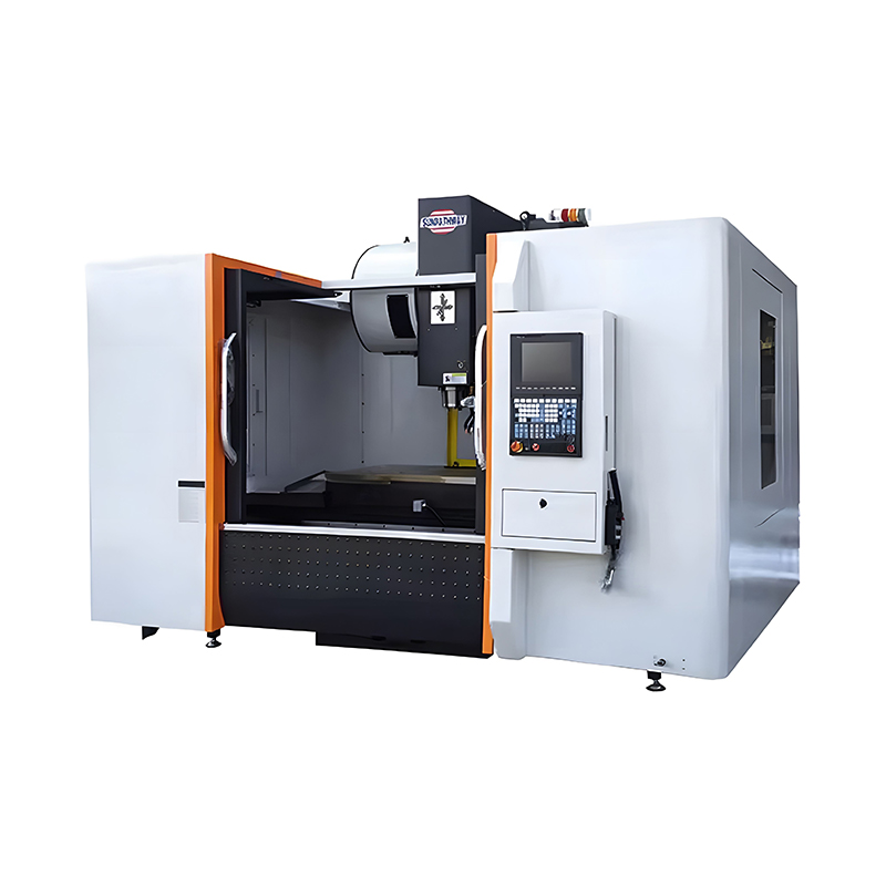
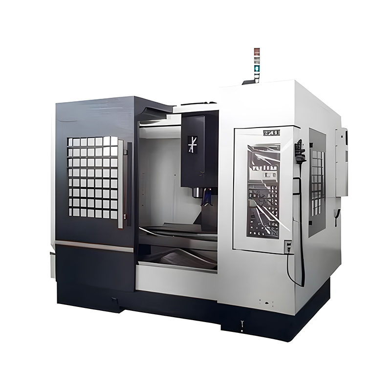 VMC850L 3-Axis Vertical Machining Center for High-Mix ProductionThis rigid vertical machining center maintains tight counterbore depth and concentricity tolerances, making it a reliable platform for shops running a high mix of precision features.View Product →
Whichever method you choose, the machine that holds the tool determines the achievable depth and diameter tolerances. A rigid three-axis vertical machining center with good spindle bearings and tight axis backlashes holds counterbore depth within +/-0.05 mm and concentricity within 0.03 mm without difficulty. That is why shops that run a high mix of such features typically standardise on a reliable vertical machining center platform.
Types of Counterbore Tools
Solid pilot counterbore
The pilot and cutter are one piece. Solid pilot counterbores are available with straight shanks for drill chucks and taper shanks for machine spindles. They are the most rigid option, deliver the best coaxiality, and are best suited to long production runs of a single size.
Interchangeable pilot counterbore
A body carries replaceable pilots and cutter blades of different diameters. This reduces tool inventory because one shank serves many sizes. Interchangeable pilots are the standard choice in job shops that machine a wide range of fastener sizes.
Reverse counterbore
Reverse or back-spotfacing tools are inserted through the pilot hole and opened behind the part so the cutter can machine the underside of a blind-mounted flange. This is used in aerospace assemblies and fixture plates where the front face is inaccessible after assembly.
Combined drill and counterbore
This two-stage tool drills the pilot hole and machines the counterbore in one pass. It is common in thin sheet-metal parts and high-volume components where the material is soft and the depth ratio is shallow.
Insert-type counterbore
Indexable insert counterbores use carbide inserts that can be rotated to a fresh cutting edge without removing the tool from the holder. They are popular on CNC lathes and machining centers for mid-to-high volume work in steel and cast iron.
Industrial Applications: Where Counterbores Show Up on Real Parts
Counterbores are not a niche feature. They are a standard part of machined product design across nearly every industry. The list below covers the most common applications:
- Automotive - cylinder head decks, transmission valve bodies, intake flanges, and bearing caps use counterbores so socket screws sit below gasket surfaces.
- Aerospace - wing skins, stringers, and splice plates use flush counterbores to reduce aerodynamic drag and avoid stress concentration at the fastener head edge.
- Mould and die making - ejector plates, guide pin pockets, and support pillar seats are counterbored so clamping screws do not interfere with the mould halves.
- Hydraulic manifolds - cartridge valve cavities and port plates use counterbores as pilot seats for O-rings and cartridge sleeves.
- Electrical enclosures - motor end caps, terminal blocks, and panel housings use counterbores so exposed screw heads do not snag cables or personnel.
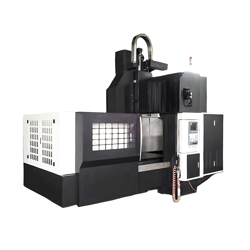
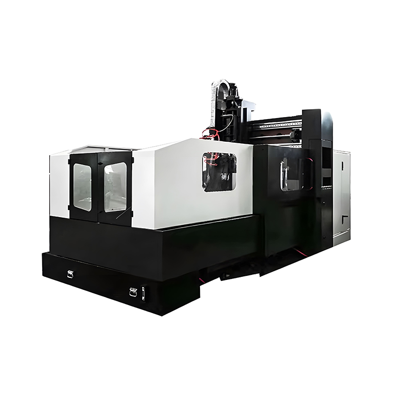
Large structural plates and machine bases are a special case. A plate that is 500 mm wide and 1,000 mm long can carry dozens of counterbored bolt holes, and the flatness of each seat affects the alignment of the whole assembly. Gantry-type milling machines handle these large workpieces in a single setup, and their long travels keep the counterbore concentric even when the plate is repositioned for a second pass.
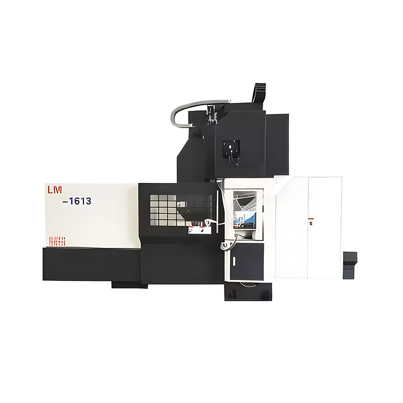 LM-1613 Heavy-Duty Gantry CNC Milling Machine for Large PartsWith long travels and high payload capacity, this gantry machine handles large structural plates and bases in a single setup, ensuring concentric counterbores across large workpieces.View Product →
Mould inserts and precision dies, by contrast, call for small-diameter counterbores with tight depth control. The counterbore that locates an ejector pin sleeve is often only 6-10 mm in diameter, yet it is expected to hold depth within +/-0.02 mm so the pin head sits exactly level with the insert face. Five-axis-capable engraving and milling centres are frequently used for this class of work because their spindles can reach into deep cavities while maintaining the flat bottom orientation.
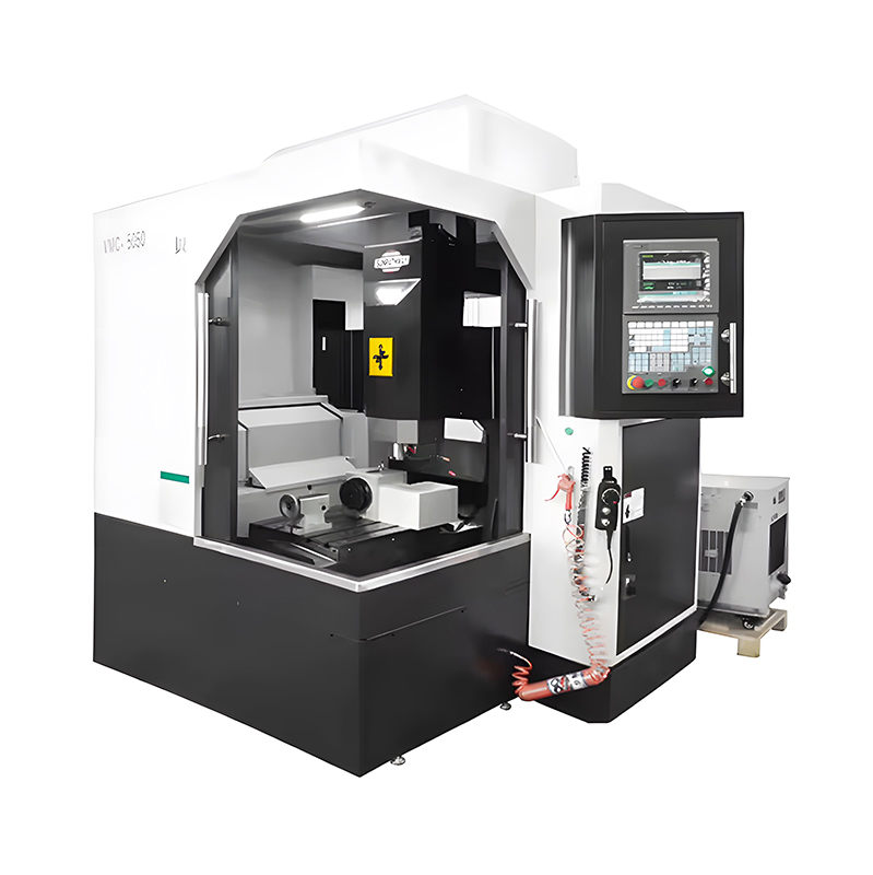 DX-5050 Multi-Axis CNC Engraving and Milling MachineDesigned for complex geometries, this machine supports 3-, 4-, or 5-axis configurations, making it suitable for mold and die work where small-diameter counterbores require tight depth control.View Product →
In mould and die production, the same plates that receive counterbored ejector housings also frequently go on to wire or sinker EDM for cavity detail after heat treatment. Conventional counterboring is done before hardening, or with an electrode after hardening; this overview of electrical discharge machining explains when EDM replaces a mechanical cutter.
Design Guidelines and Engineering Tolerances
The tolerances assigned to a counterbore depend entirely on its function. A counterbore that simply seats a cover screw can be generous; a counterbore that locates a bearing or a cartridge valve is not.
| Parameter | Typical Tolerance | Notes |
|---|---|---|
| Counterbore diameter | +0.1 / +0 mm | A clearance fit for the fastener head; tighter if locating a component. |
| Counterbore depth | +/-0.1 mm | Holds the head flush or sub-flush. Reduce to +/-0.05 mm for sealing faces. |
| Concentricity to pilot | 0.05-0.1 mm | Achievable with a piloted tool; check with a concentricity gauge or CMM. |
| Bottom flatness | 0.02-0.05 mm | Critical for uniform clamp load; a spring pass improves flatness. |
| Bottom surface finish | 1.6-3.2 um Ra | Smooth enough to prevent galling under the fastener head. |
- Keep at least one counterbore diameter of wall material between the counterbore edge and the part edge to avoid breakout.
- On castings or forgings, always spotface before final counterboring so the cutter starts from a flat reference.
- For blind counterbores, leave a minimum of 3 mm of material under the bottom unless the print specifically requires a reduced section.
- Always add a small chamfer or break the edge at the counterbore mouth; sharp edges raise material that can interfere with O-ring sealing.
Common Counterboring Mistakes and How to Avoid Them
- Wrong pilot size - a loose pilot lets the cutter wobble and produces an oversized, off-center counterbore. Fix: measure the drilled hole and select a pilot diameter that fits within a close sliding fit, typically an H8 tolerance class.
- Incorrect depth assumption - counterboring to the nominal head height leaves the fastener head protruding when gaskets or coatings are present. Fix: add a minimum of 0.3 mm extra depth and confirm against the actual fastener batch.
- Excessive feed causing bell-mouth - high feed deflects the tool and enlarges the top of the counterbore. Fix: reduce feed, use a stubbier tool, or add a finishing pass at low feed.
- Chip packing in blind counterbores - chips trapped under the cutter score the flat bottom. Fix: use interrupted pecking or helical ramping to evacuate chips.
- Tool runout - a worn collet or a long tool extension creates chatter marks and an oversize bore. Fix: re-cut the tool seat, use a shrink-fit holder, or switch to a shorter end mill.
- Skipping the deburr - a sharp upper edge rolls into a burr that interferes with washers and seals. Fix: program a 0.2 mm chamfer or run a deburring pass before changing tools.
- Assuming nominal bolt size equals head size - an M8 screw has a 13 mm head, not an 8 mm head. Fix: always check the maximum head diameter on the fastener drawing before entering the counterbore diameter into the CAM system.
Frequently Asked Questions About Counterbores
What is the difference between a counterbore and a countersink?
A counterbore has a flat bottom and parallel walls and is sized to enclose the cylindrical head of a socket or cap screw. A countersink has a conical wall and seats a flat-head screw so that the top of the screw is flush with the part surface.
How do you specify a counterbore on a drawing?
Use the standard counterbore callout symbol with the counterbore diameter, depth, and pilot hole. A typical note is "12.5 dia x 8.2 deep over 8 dia through". The depth is measured from the front face of the part.
How deep should a counterbore be?
Set the depth equal to the fastener head height plus 0.3-0.5 mm of clearance if the head must sit fully below the surface. If the head should sit flush, use the exact head height plus a small allowance for coatings and tolerances.
Can a CNC milling machine produce a counterbore without a special tool?
Yes. A standard flat-end mill combined with circular interpolation (G02/G03) cuts a counterbore to any diameter that is larger than the end mill. This method is used in almost every CNC machine shop and requires only the correct depth programming and a spring pass on the flat bottom.
What is a spotface compared with a counterbore?
A spotface is a shallow flat-bottomed counterbore, usually 0.5-2 mm deep, that provides a flat bearing surface on a rough part. It does not enclose the fastener head along its height; it only levels the seating area.
How do you measure a counterbore depth accurately?
Use a depth micrometer with a flat contact tip, a dial bore gauge with a reference surface, or a coordinate measuring machine. For production inspection, a dedicated go/no-go depth gauge with the correct step height gives the fastest repeatable result.
Counterbores are not exotic geometry. They are everyday features that keep assemblies flat, support sealing, and prevent sharp bolt protrusions. The three things that matter most are the real head dimensions of the fastener, the depth tolerance that your assembly actually requires, and the rigidity of the tool path that produces the flat bottom. Get those three right, and the counterbore will never be the reason a part gets rejected.
If you are specifying a CNC machine to handle counterbore-heavy production, or you need a machine recommendation for a specific material and batch size, tell our engineering team what you plan to run and start the conversation through our contact page.
PREV:No previous article
NEXT:What Is a Clearance Fit? Learn Types, Tolerances, and CNC Machining Guide
NEXT:What Is a Clearance Fit? Learn Types, Tolerances, and CNC Machining Guide
Interested in cooperation or have questions?
News
-
-
A clearance fit is an assembly condition in which the minimum hole diameter is always larger than the maximum shaft diameter. In one sentence: the two mating parts are separated by a guaranteed positive gap, so they can slide, ro...
READ MORE -
Heat treatment is a controlled thermal process that changes the mechanical properties of metal by heating it to a specific temperature, holding it there, and then cooling it at a rate chosen to produce a desired internal structur...
READ MORE -
An EDM machine, also called an electrical discharge machining machine, uses controlled sparks to erode electrically conductive metal without direct contact between the tool and the workpiece. The workpiece is submerged in a diele...
READ MORE
Related Products

-
Factory Address
Zhaxi Township Industrial Park, Nantong City, Jiangsu Province, China (west of Huaneng Power Plant)
-
Phone
+86-13615235768
+86-15950816906
-
Fax
+86-513-85632766
-
Email
pan.director@sunwayer.com
Stay Connected
lf you can't find the answer you're looking for, chat with our friendly team.
Stay Connected
Copyright © Nantong Sunway Science and Technology Development Co., Ltd. All Rights Reserved.
China CNC Equipment Manufacturers
Custom CNC Equipment Factory
