


 русский
 Español

A die insert arrives on the inspection bench. The drawing specifies the bottom face as datum A, the rear face as datum B, and the left face as datum C. Every pocket, hole, and contour is located from this three-plane system. The ...
READ MORE
What Is a Datum in Engineering? Understanding Datums, DRFs, and GD&T Basics
Content
- 1 The Formal Definition of a Datum in Engineering
- 2 Datum vs. Datum Feature: What Exactly Is the Difference?
- 3 The Datum Reference Frame: How Primary, Secondary, and Tertiary Datums Work Together
- 4 Why Datums Matter in CNC Machining and Setup
- 5 How Datums Are Used in Inspection and Measurement
- 6 Datums in CAD, CAM, and CNC Programming: From Model to G-Code
- 7 Datum Selection Best Practices: Advice from the Shop Floor
- 8 Common Datum Mistakes and Their Real Consequences
- 9 Applying Datums with the Right Equipment: Machining, EDM, and Large Parts
- 10 Frequently Asked Questions About Datums in Engineering
- 10.1 What is a datum in simple terms?
- 10.2 What is the difference between a datum and a tolerance?
- 10.3 What is a datum reference frame in GD&T?
- 10.4 How many datums does a part need?
- 10.5 Can a hole be used as a datum feature?
- 10.6 What is the 3-2-1 rule in GD&T?
- 10.7 Why does the order of datums matter?
A die insert arrives on the inspection bench. The drawing specifies the bottom face as datum A, the rear face as datum B, and the left face as datum C. Every pocket, hole, and contour is located from this three-plane system. The milling operator, the EDM programmer, and the CMM inspector must each interpret those three letters in the same way, because the same part will pass through all three of their workstations before it ships.
Here is the direct answer to "what is a datum in engineering": a datum is a theoretically exact reference point, line, plane, axis, or a combination of these, from which the location, orientation, and form of manufactured features are defined and verified. It is the agreed zero point for all measurements. Datums are the foundation of geometric dimensioning and tolerancing (GD&T), and the principles behind them are documented in standards such as ASME Y14.5-2018 and ISO 5459. Choose the right datum, and machining, inspection, and assembly stay aligned. Choose it poorly, and good parts get rejected while defective parts move on.
The Formal Definition of a Datum in Engineering
In formal engineering terms, a datum is not a physical object. It is a theoretically perfect plane, line, point, or axis that serves as a reference for locating other features. The physical feature on the part that produces the datum is called the datum feature. Because every real surface has roughness and form error, the drawing-level datum is realized by placing the datum feature against a datum feature simulator: a precision surface plate, a gage pin, a chuck, a mandrel, or a fixture surface that is accurate to a much smaller tolerance than the part itself.
Understanding the different datum forms is the first step to reading any GD&T drawing correctly. The table below summarizes the four common datum forms and how they are established in practice.
| Datum Form | Established By | Typical Applications |
|---|---|---|
| Datum plane | Precision flat surface, such as a surface plate, machine table, or fixture plate | Mounting bases, housing flanges, reference faces for machining and inspection |
| Datum axis | Precision bore contacted by a mandrel, expanding collet, or gage pin | Cylindrical parts, rotating shafts, bore-centered hole patterns |
| Datum line | Line of contact between a cylinder and a vee block, or between two planes | Long prismatic parts, sheet metal profiles, edge-guided features |
| Datum point | Precision cone seat, ball, or spherical support | Sphere-based positioning, optical components, instrument references |
Datum vs. Datum Feature: What Exactly Is the Difference?
New engineers often use "datum" and "datum feature" interchangeably, and that causes genuine disputes between machining and inspection. The datum is the theoretical reference shown in the feature control frame. The datum feature is the actual physical feature on the part that you can touch with your fingers or a probe. Between them sits the datum feature simulator: the element of the fixture, machine, or measuring device that contacts the datum feature and turns an imperfect surface into a usable reference.
Take a motor housing that calls out datum A on its underside. The real surface contains roughness, waviness, and flatness error. When it is placed on a granite surface plate, only the three highest points carry the load. The plane passing through those high points is the datum plane. This is why the form of the datum feature must be controlled: a wavy face creates datum shift and unstable measurements, no matter how accurate the rest of the part is.
- Datum: theoretical, exact, and defined only on the drawing.
- Datum feature: the actual surface, hole, slot, or edge on the machined part.
- Datum feature simulator: the plate, gage pin, mandrel, chuck, or vee block that contacts the datum feature.
The Datum Reference Frame: How Primary, Secondary, and Tertiary Datums Work Together
A single datum constrains only part of a component's six degrees of freedom: three translations along the X, Y, and Z axes, and three rotations around those axes. To locate a part completely, GD&T uses a datum reference frame, or DRF, built from up to three mutually perpendicular datum planes. The priority order is written directly in the feature control frame: the first letter is the primary datum, the second letter is the secondary datum, and the third letter is the tertiary datum.
The classic 3-2-1 rule makes this easy to visualize. The primary datum touches the part at three points and removes three degrees of freedom. The secondary datum touches at two points and removes two more. The tertiary datum touches at one point and removes the last one. That is why the bottom face, one long side face, and one short end face are the standard datum scheme for prismatic components.
| Level | Contact Points | Degrees of Freedom Removed | Typical Feature |
|---|---|---|---|
| Primary datum | 3 | Two rotations and one translation | Bottom face or largest functional face |
| Secondary datum | 2 | One rotation and one translation | Rear face or longest side face |
| Tertiary datum | 1 | One translation | Short side face or end face |
Why Datums Matter in CNC Machining and Setup
Machining accuracy is essentially the ability to cut features where the drawing says they should be, and that is a datum problem. Before the tool moves, the operator or the workholding fixture must establish the same datum relationship that the designer defined. On a CNC vertical machining center, this usually means aligning the part against precision-machined reference edges, using a probing cycle, or seating it on a qualified fixture. The work offset, commonly G54 in G-code programs, stores the location of the part origin in the machine coordinate system.
The risk appears when machining and design use different references. If the drawing dimensions are taken from datum A, a machined face, but the operator sets the origin on a raw as-cast edge, every feature inherits the variation of that cast edge. A positional tolerance of 0.05 mm can be completely consumed by a datum error of 0.2 mm. This is why experienced shops machine the datum features first in the routing, then use them as the reference for all finish milling, drilling, and boring.
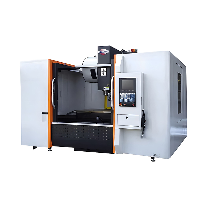
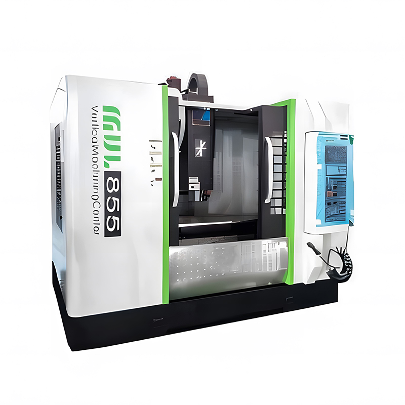
A stable machine platform makes it possible to repeat a datum from the first part to the thousandth part. High repeatability requires a rigid spindle, thermally stable castings, and a precisely ground worktable. These are the characteristics built into the VMC850L high-speed three-axis CNC vertical machining center, which is designed for high-repeatability milling of precision parts in mold, die, automotive, and general metalworking environments.
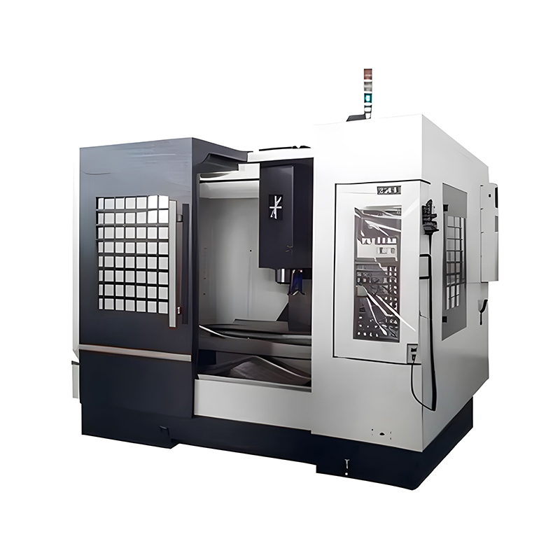 VMC850L High-Speed 3-Axis CNC Vertical Machining CenterThe VMC850L's rigid spindle and stable platform ensure high repeatability, making it a reliable choice for establishing datums that remain consistent from the first part through mass production.View Product →
How Datums Are Used in Inspection and Measurement
Inspection reverses the machining question. Instead of establishing a datum in order to cut features, the inspector establishes a datum in order to measure features. On a coordinate measuring machine, the part is aligned by probing the datum features. The software constructs datum planes and axes, builds the datum reference frame, and then reports every measured feature relative to that frame. The measured value of a hole location is meaningless without the datum frame behind it.
Hard gauging follows the same philosophy without software. A part is seated against a surface plate, vee blocks, or a dedicated fixture that contains the datum feature simulators, and the inspector measures with height gauges, dial indicators, and pins. The inspection result depends entirely on how each datum feature is simulated, so the datum sequence on the drawing must be replicated exactly. When that sequence changes between the machine setup and the CMM program, the two inspection methods can disagree, even when both appear to follow the drawing.
| Method | How Datum Is Established | Practical Accuracy Range |
|---|---|---|
| CMM | Probes datum features and constructs planes and axes mathematically | 0.5 to 5 micrometers, depending on machine, probe, and environment, with machine performance checked per ISO 10360 |
| Surface plate with height gauge | Precision granite plate acts as the primary plane simulator | 2 to 10 micrometers, depending on gauge quality and operator skill |
| Dedicated hard gauge | Machined fixture replicates the complete datum reference frame | Limited by fixture machining accuracy and wear over time |
Datums in CAD, CAM, and CNC Programming: From Model to G-Code
Designers create datum planes in CAD software to define sketches, features, and assembly constraints. Those planes play exactly the same role as drawing datums: they give every feature an unambiguous geometric home. The CAM programmer then turns the CAD model into toolpaths, and the origin of the CAM coordinate system should match the datum scheme on the drawing. When the program is posted and uploaded to the machine, the G54 work offset shifts the machine home position to that datum origin.
A clean workflow for CNC shops is simple: use the primary datum face for the Z origin, the secondary datum face for the X or Y origin, and the tertiary datum face for the remaining axis. Keep the CAM origin identical to the inspection origin. If those three origins do not match, a part can be machined perfectly and still fail inspection because the measurement coordinate system is rotated relative to the machining coordinate system.
Datum Selection Best Practices: Advice from the Shop Floor
Every datum decision is a trade-off between design function, manufacturing access, and inspection repeatability. The rules below prevent most datum-related failures seen in mold, die, and precision machining shops.
- Choose functional surfaces first. The datum features should mimic how the part is located or mated in its final assembly.
- Prefer large, rigid, machined surfaces for the primary datum. A bigger surface area gives stable seating and reduces sensitivity to local defects.
- Machine the datum features in an early operation. Finish the reference faces before cutting the features that are located from them.
- Keep one datum scheme from design through to inspection. Do not reorder the letters to make measurement easier.
- Control the form of the datum feature. Flatness and perpendicularity tolerances directly control the amount of datum shift.
- Use accessible features. The datum feature must be reachable by the machine setup, the fixture, and the CMM probe.
- Avoid flexible features as datums. Thin walls, sheet metal edges, and long unsupported spans create unstable references.
- Validate early. Measure the first article and compare the datum simulation between the machine and the CMM before starting full production.
Common Datum Mistakes and Their Real Consequences
Most quality problems traced back to datums are not caused by bad machining. They are caused by ambiguous, impractical, or inconsistent datum definitions. This table lists the failures most often seen in precision machining and mold manufacturing.
| Mistake | Consequence | Correction |
|---|---|---|
| Using an unmachined cast or forged surface as a primary datum | Unstable seating and large deviation in every machined feature | Machine the reference face before finish operations |
| Reordering datum features during inspection | Parts rejected by CMM but accepted by hard gauge, or the reverse | Keep the same datum sequence on the drawing, fixture, and CMM program |
| No form control on the datum feature | Datum shift varies from part to part | Add flatness and perpendicularity tolerances to the datum feature |
| Using a thin wall or sheet metal edge as a datum | Measured variation caused by elastic deflection | Relocate the datum or stiffen the feature |
| Mismatching the CAM origin with the drawing datums | Features machined at correct size but wrong position | Align the CAM coordinate system to the datum reference frame |
Applying Datums with the Right Equipment: Machining, EDM, and Large Parts
Different manufacturing processes interpret datums in their own way, but the principle stays the same: the electrode, the workpiece, and the finished cavity must share one reference system. In sinker EDM, the electrode is positioned relative to the datum edges of the workpiece. If those datum edges are not square, flat, and clean, the cavity location drifts even when the electrode itself is perfect. In mold shops, a compact and accurate die-sinking machine such as the CNC430 small CNC electrical discharge machine for metal mould making helps operators set the electrode origin from the workpiece datum features quickly and repeatably.
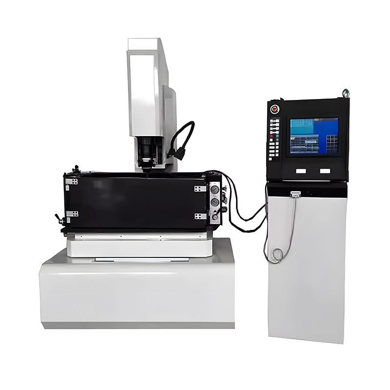 CNC-430 Small CNC EDM Machine for Mould MakingThis compact EDM machine helps operators quickly set electrode origins from workpiece datum features, ensuring accurate cavity locations in small-scale mold and die production.View Product →
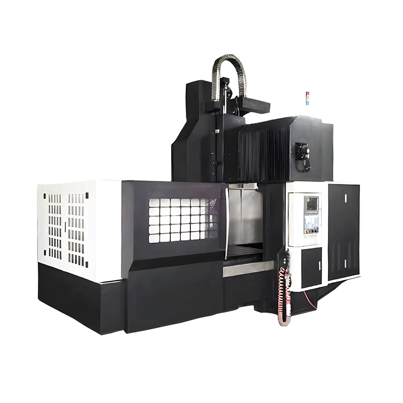
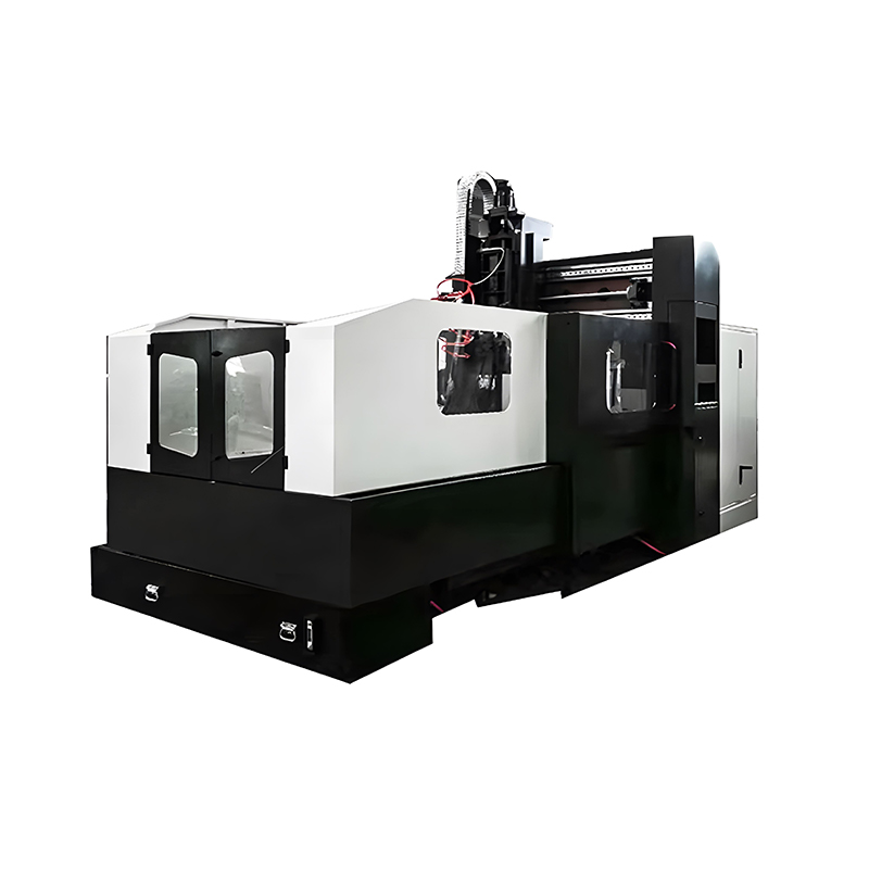
Large plates and gantry-sized workpieces add another constraint. A part weighing several tons may have datum faces that are meters apart, and the machine structure must maintain the relationship between those faces and the cutter. Gantry-style milling machines with wide travel and rigid frames minimize the geometric error between the datum face and the machined feature. The LM1613 high-precision metal milling gantry CNC machine is designed for exactly this kind of datum-critical large-part work, with a structure built to hold accuracy over long travels.
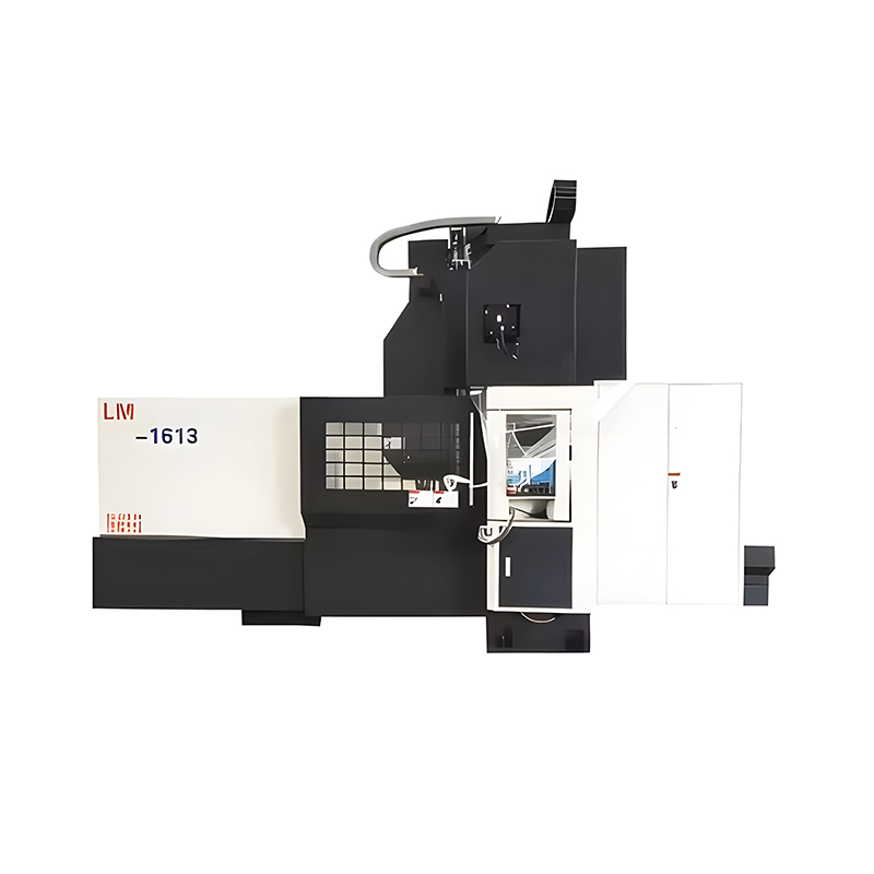 LM-1613 High-Precision Gantry CNC Milling MachineThe LM-1613's rigid gantry structure and long travel minimize geometric error between datum faces and the cutter, making it ideal for large, datum-critical workpieces.View Product →
For readers who work with mold cavities and hardened materials, a practical overview of EDM explains how discharge machining fits into a datum-based manufacturing workflow. Whatever process you choose, the datum comes first: machine it, protect it, and measure from it.
Frequently Asked Questions About Datums in Engineering
What is a datum in simple terms?
A datum is a fixed, theoretically exact reference point, line, plane, or axis used to measure and locate everything else on a part. Think of it as the starting line on a ruler: every measurement starts from that line, and everyone measuring the same part uses the same line.
What is the difference between a datum and a tolerance?
A datum is the reference, and a tolerance is the allowed deviation from that reference. For example, a hole center may be located 10 mm from datum B with a positional tolerance of 0.2 mm. The datum defines where the hole should be, and the tolerance defines how far from that ideal location it may actually land.
What is a datum reference frame in GD&T?
A datum reference frame is a coordinate system made of up to three mutually perpendicular planes, established by the primary, secondary, and tertiary datum features in that order of priority. The DRF constrains the six degrees of freedom of a rigid part so that every feature can be measured from one unique reference system.
How many datums does a part need?
It depends on the geometry and the design function. A flat plate may need only one primary datum plane. A rectangular prismatic part typically needs three datums in a 3-2-1 scheme. A cylindrical part usually needs a datum axis plus a datum plane to locate the end face. Use as many datums as the drawing needs to remove ambiguity, and no more.
Can a hole be used as a datum feature?
Yes. A bore is one of the most common datum features for cylindrical parts. The datum axis is established by inserting a precision mandrel, expanding collet, or gage pin into the bore. Hole datums are widely used for shafts, rings, pulleys, and any part that assembles onto a spindle or pilot.
What is the 3-2-1 rule in GD&T?
The 3-2-1 rule explains how a datum reference frame is established: the primary datum contacts the part at three points, the secondary datum at two points, and the tertiary datum at one point. These six contact points constrain all six degrees of freedom of a rigid part, three translations and three rotations.
Why does the order of datums matter?
The order tells the machinist and the inspector which feature to constrain first. The primary datum removes the most degrees of freedom and establishes the dominant orientation of the part. If you swap the order, the part sits differently in space, and measurements of critical features will shift even though the part itself has not changed.
Datums are not an abstract GD&T topic reserved for the drawing office. They are an operational reality for every shop that mills, measures, and assembles parts, because they decide where the tool goes, where the probe goes, and where the part finally sits in its assembly.
Before you cut metal on a new component, spend ten extra minutes reviewing the datum scheme with the production engineer. If you are selecting new equipment and need a machine that can hold a tight datum relationship over long cycles, tell us about your part and your drawing requirements on the contact page, and Sunway will help you find a machine configuration matched to your datum and tolerance needs.
PREV:No previous article
NEXT:What Is a Counterbore? Complete Guide to Flat-Bottomed Holes and Machining
NEXT:What Is a Counterbore? Complete Guide to Flat-Bottomed Holes and Machining
Interested in cooperation or have questions?
News
-
-
A counterbore is a cylindrical, flat-bottomed recess machined concentrically around a through hole so that a bolt head, cap screw, or nut sits flush with - or slightly below - the surface of a workpiece. The same word also names ...
READ MORE -
A clearance fit is an assembly condition in which the minimum hole diameter is always larger than the maximum shaft diameter. In one sentence: the two mating parts are separated by a guaranteed positive gap, so they can slide, ro...
READ MORE -
Heat treatment is a controlled thermal process that changes the mechanical properties of metal by heating it to a specific temperature, holding it there, and then cooling it at a rate chosen to produce a desired internal structur...
READ MORE
Related Products


-
Factory Address
Zhaxi Township Industrial Park, Nantong City, Jiangsu Province, China (west of Huaneng Power Plant)
-
Phone
+86-13615235768
+86-15950816906
-
Fax
+86-513-85632766
-
Email
pan.director@sunwayer.com
Stay Connected
lf you can't find the answer you're looking for, chat with our friendly team.
Stay Connected
Copyright © Nantong Sunway Science and Technology Development Co., Ltd. All Rights Reserved.
China CNC Equipment Manufacturers
Custom CNC Equipment Factory
