

 русский
 Español
What Does Machining Mean? The Direct Answer Machining is a subtractive manufacturing process in which material — most commonly metal — is precisely removed from a workpiece using cutting tools and controlled mechanical force, le...
READ MORE
How does a vertical machine work?
Content
- 1 How a Vertical Machine Works: The Core Principle
- 2 The Spindle: Heart of the Vertical Machining Center
- 3 Axis Movement: How the Machine Positions the Tool
- 4 The CNC Controller: Brain of the Vertical Machining Center
- 5 Automatic Tool Changers and Tool Management
- 6 Workholding: Keeping the Part Stationary While Cutting
- 7 Coolant Systems and Their Role in Vertical Machining
- 8 4th and 5th Axis: Expanding What Vertical Machining Centers Can Do
- 9 Common Operations Performed on Vertical Machining Centers
- 10 Thermal Stability and Compensation in Vertical Machining Centers
- 11 Vertical Machining Centers vs. Horizontal Machining Centers: When to Use Which
- 12 Materials Commonly Machined on Vertical Machining Centers
- 13 Pallet Changers and Automation Integration
- 14 Key Specifications to Evaluate When Selecting Vertical Machining Centers
How a Vertical Machine Works: The Core Principle
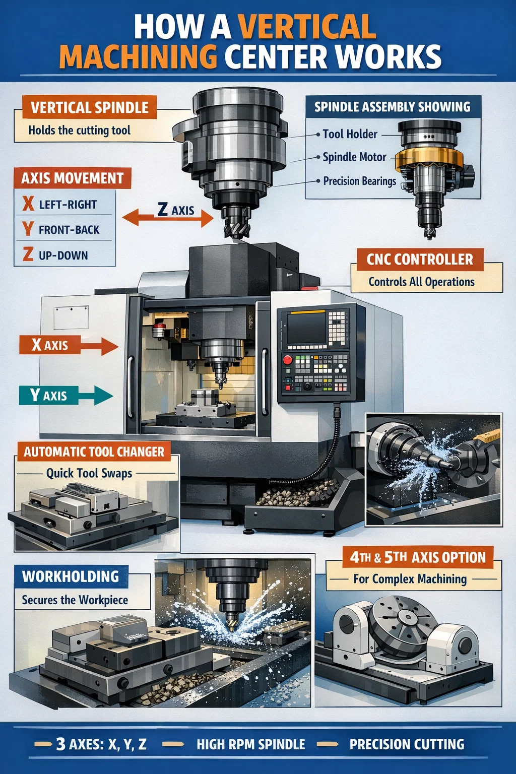
A vertical machine — specifically a vertical machining center (VMC) — works by holding a cutting tool in a vertically oriented spindle that moves downward into a stationary or repositionable workpiece. The spindle axis runs perpendicular to the ground, meaning the tool approaches the material from above. This geometry makes it highly effective for flat parts, mold cavities, and components that require drilling, milling, or tapping on their top faces. Most vertical machining centers operate across three primary linear axes: X (left-right), Y (front-back), and Z (up-down), with many modern machines adding a fourth or fifth rotary axis for complex contouring work.
Unlike horizontal machining centers where the spindle is parallel to the floor, vertical machining centers position the cutting tool above the workpiece. Chips and coolant fall away from the cutting zone by gravity, which reduces re-cutting of material and generally improves surface finish quality. This is the foundational mechanical advantage of a vertical orientation in precision metal cutting.
The Spindle: Heart of the Vertical Machining Center
The spindle is the rotating component that drives the cutting tool. In vertical machining centers, the spindle is mounted in a vertical column and moves primarily along the Z-axis. Spindle speed, measured in RPM, directly determines material removal rate and surface finish. Entry-level vertical machining centers typically offer spindle speeds ranging from 6,000 to 12,000 RPM, while high-speed machining centers can exceed 40,000 RPM for aluminum and non-ferrous alloys.
Spindle taper is another critical specification. The most common standards in vertical machining centers include:
- CAT 40 and CAT 50 — widely used in North American industry; CAT 40 suits lighter cuts and smaller machines, CAT 50 handles heavier stock removal.
- BT 30, BT 40, BT 50 — Japanese standard, geometrically similar to CAT but with a different flange design; common in Japanese-built vertical machining centers.
- HSK (Hollow Shank Taper) — used in high-speed applications because of its shorter, more rigid interface; critical when spindle speeds exceed 20,000 RPM.
Spindle bearings are precision-ground angular contact ball bearings or ceramic hybrid bearings. The bearing arrangement determines thermal stability and maximum safe speed. High-quality vertical machining centers use oil-air lubrication or grease-packed sealed bearings to maintain consistent spindle temperatures across long production runs.
Spindle Motor Types and Their Effect on Cutting Performance
Vertical machining centers use either belt-driven or direct-drive (built-in motor) spindle configurations. Belt-driven spindles are cost-effective and easier to repair, but they introduce some vibration that can limit surface finish quality at high feed rates. Direct-drive or integrated motor spindles — often called "motorized spindles" — eliminate mechanical transmission losses entirely, providing smoother rotation, lower vibration, and faster acceleration. A direct-drive spindle on a mid-range vertical machining center can accelerate from 0 to 12,000 RPM in under one second, reducing non-cutting time significantly during high-volume production runs.
Axis Movement: How the Machine Positions the Tool
Vertical machining centers use a Cartesian coordinate system to position the cutting tool relative to the workpiece. Each axis is driven by a servo motor connected to a precision ballscrew. The CNC controller sends position commands to each axis servo, which compares actual position (measured by a linear encoder or rotary encoder on the ballscrew) against the commanded position and adjusts accordingly. This closed-loop feedback system is what gives vertical machining centers their repeatability.
Typical positioning accuracy for production-grade vertical machining centers is ±0.002 mm (0.0001 inches), with high-precision models achieving ±0.001 mm. Repeatability — the machine's ability to return to the same position — is often tighter than positioning accuracy, typically ±0.001 mm on quality machines.
Rapid Traverse vs. Feed Rate
Vertical machining centers move at two fundamentally different speeds. Rapid traverse is the maximum speed at which the axes move when no cutting is occurring — repositioning between features, for example. Modern vertical machining centers have rapid traverse rates of 30 to 60 meters per minute (roughly 1,200 to 2,400 inches per minute). Feed rate, on the other hand, is the controlled speed at which the tool engages the material, programmed in the G-code and typically ranging from 50 mm/min for hard steels to several thousand mm/min for aluminum finishing cuts. Faster rapids reduce cycle time without affecting part quality, which is why machine builders compete heavily on this specification.
Linear Guideways vs. Box Ways
The method by which the moving components slide along their axes has a direct impact on machine performance. Vertical machining centers use one of two main guideway systems:
- Linear roller or ball guideways — low friction, high speed capability, excellent for precision work and high-speed machining. Most common in modern vertical machining centers designed for aluminum and light steel work.
- Box ways (flat or dovetail ways) — higher contact area, better vibration damping, more suited for heavy interrupted cuts in hard materials like cast iron or stainless steel. Slower rapids but more rigid under extreme cutting forces.
Many job shops running diverse work choose linear guideway machines for their versatility. Die and mold shops cutting hardened tool steels often prefer box way machines for the damping characteristics.
The CNC Controller: Brain of the Vertical Machining Center
Every vertical machining center is controlled by a CNC (Computer Numerical Control) unit that interprets G-code programs and converts them into real-time servo commands. The controller coordinates all axes simultaneously, manages spindle speed, controls the automatic tool changer, and monitors machine conditions through a network of sensors.
Leading CNC controllers used in vertical machining centers include Fanuc, Siemens SINUMERIK, Mitsubishi M800, and Heidenhain TNC. Each has distinct strengths. Fanuc controllers dominate globally with a market share estimated above 60%, primarily because of their reliability, extensive documentation, and widespread service availability. Heidenhain is preferred in European precision shops for its conversational programming interface and exceptional contouring accuracy.
The look-ahead function in modern CNC controllers is particularly important for vertical machining centers running complex 3D contours. Look-ahead reads dozens or hundreds of upcoming blocks simultaneously and pre-calculates the required deceleration to maintain accuracy through direction changes — preventing tool marks and maintaining programmed tolerances even at aggressive feed rates.
G-Code and How It Drives the Machine
G-code is the standardized language that instructs the CNC what to do. A G00 command triggers rapid positioning. G01 starts a linear interpolated cut at a specified feed rate. G02 and G03 generate clockwise and counterclockwise circular arcs. Canned cycles like G81 (drilling), G84 (tapping), and G73 (peck drilling) automate repetitive operations with a single block of code. M-codes handle auxiliary functions: M03 starts the spindle clockwise, M06 initiates an automatic tool change, M08 activates coolant. Together, these commands give operators complete control over every movement and function of the vertical machining center.
Automatic Tool Changers and Tool Management
One of the defining features of vertical machining centers — as opposed to manual mills or basic CNC machines — is the automatic tool changer (ATC). The ATC stores a library of pre-set tools in a carousel or chain-type magazine and swaps them into the spindle without operator intervention, typically in 2 to 8 seconds per tool change.
Standard tool magazine capacities for vertical machining centers range from 16 to 40 tools on most production models, with extended-capacity magazines reaching 60, 100, or even more positions on larger machines designed for complex parts requiring many operations. The ATC mechanism uses a mechanical arm that extracts the current tool from the spindle, rotates to the next tool position, and inserts the new tool — all during a coordinated Z-axis retract movement to minimize non-productive time.
Tool length offsets and tool radius compensation values are stored in the CNC controller's offset table. Operators or presetting equipment measure each tool's length before loading it, and the controller automatically applies these offsets to ensure the programmed Z-depth is achieved regardless of variations between individual tool holders.
Tool Life Management in Production Environments
Advanced vertical machining centers integrate tool life management through the CNC controller. The system tracks the number of parts run or total cutting minutes accumulated by each tool and automatically substitutes a sibling tool (a duplicate in a different magazine pocket) when the primary tool reaches its programmed life limit. This eliminates surprise tool failures that can scrap expensive workpieces and prevents unplanned machine stops during lights-out production shifts.
Workholding: Keeping the Part Stationary While Cutting
The worktable of a vertical machining center is the platform on which the workpiece is secured. T-slots machined into the table surface accept standard hold-down hardware, vises, and fixture plates. Table size varies considerably by machine class — a small vertical machining center might have a 500 × 400 mm table, while large bridge-type vertical machining centers have tables exceeding 2,000 × 1,000 mm and carry loads of several tons.
Common workholding methods used with vertical machining centers include:
- Precision machine vises — fast setup for prismatic parts; jaw widths typically range from 100 mm to 200 mm for standard vertical machining center vises.
- Custom fixtures — designed for specific parts to locate multiple datums simultaneously; critical for high-volume production where setup time must be minimized.
- Modular fixturing systems (e.g., Carr Lane, Lang Makro) — reusable components that can be reconfigured quickly for prototype and low-volume work.
- Vacuum chucks — used for thin sheet parts or non-ferrous materials where clamping force could distort the workpiece.
- Zero-point clamping systems — allow pallets with pre-loaded parts to be exchanged on the table in seconds with sub-0.005 mm repeatability.
Workholding quality directly affects the accuracy of finished parts. Poorly clamped workpieces vibrate during cutting, producing chatter marks on the surface and dimensional errors in the finished part. The rigidity of the entire workholding setup — from table to fixture to part — must match the cutting forces the tool generates.
Coolant Systems and Their Role in Vertical Machining
Coolant serves two purposes in vertical machining centers: temperature control and chip evacuation. Heat generated at the cutting zone softens tool edges, accelerates wear, and causes thermal expansion in the workpiece that shifts dimensions. Coolant applied at the cutting edge carries heat away before it transfers into the tool or part.
Vertical machining centers use several coolant delivery methods depending on the application:
- Flood coolant — the most common; nozzles around the spindle direct coolant flow toward the tool-workpiece interface at pressures of 2–10 bar.
- Through-spindle coolant (TSC) — coolant is delivered internally through the spindle and tool at pressures of 40–70 bar; essential for deep-hole drilling and long-reach tools where external coolant cannot reach the cutting zone effectively.
- Minimum quantity lubrication (MQL) — a near-dry method that delivers a fine oil mist directly to the cutting zone; reduces coolant consumption by up to 95% compared to flood coolant; suitable for aluminum, cast iron, and some steels.
- Air blast — used when coolant would cause thermal shock in certain materials or when dry machining is required; less effective for heat management but avoids coolant contamination.
Chip management is closely linked to coolant. In vertical machining centers, chips fall onto the worktable and must be flushed or conveyed away. Most machines include chip conveyors — either auger-type for fine chips or hinge-belt type for long, stringy chips — that carry material out of the work envelope into a collection bin. Effective chip management prevents chip re-cutting, which damages surfaces and accelerates tool wear.
4th and 5th Axis: Expanding What Vertical Machining Centers Can Do
Standard vertical machining centers operate in three linear axes. Adding rotary axes — typically a rotary table (A or B axis) or a tilting rotary table (simultaneous 4+1 or full 5-axis) — dramatically expands the range of geometries that can be machined in a single setup. This capability reduces the number of setups required for complex parts, which directly reduces cumulative positioning error and total production time.
5-axis vertical machining centers can machine complex impellers, turbine blades, orthopedic implants, and mold cores that would require five or more setups on a 3-axis machine. A titanium hip cup that might require six separate fixture setups on a 3-axis VMC can often be completed in a single setup on a 5-axis vertical machining center, cutting total setup and handling time from hours to minutes.
The distinction between 3+2 machining (positioning rotary axes, then cutting with linear axes only) and simultaneous 5-axis machining (all five axes moving together during the cut) is important. Simultaneous 5-axis motion allows the tool to maintain optimal contact angle with curved surfaces throughout the cut, producing better surface quality with fewer passes. However, it requires more sophisticated CAM software and more capable CNC controllers to execute correctly.
Common Operations Performed on Vertical Machining Centers
Vertical machining centers are among the most versatile metal cutting platforms available. The following table summarizes the primary operations they perform, along with typical tooling and achievable tolerances:
| Operation | Typical Tooling | Achievable Tolerance | Common Applications |
|---|---|---|---|
| Face Milling | Indexable face mill, 50–100 mm dia. | ±0.01 mm flatness | Squaring stock, surface preparation |
| Pocket Milling | Solid carbide end mills, 6–25 mm dia. | ±0.02–0.05 mm | Mold cavities, enclosures, brackets |
| Drilling | Carbide twist drills, indexable drills | ±0.05 mm position, IT9–IT10 dia. | Bolt holes, coolant passages |
| Boring | Single-point boring bars, fine boring heads | ±0.005 mm diameter, IT6–IT7 | Bearing bores, precision fits |
| Tapping | Spiral flute or spiral point taps | 6H thread tolerance class | Threaded fastener holes |
| Contouring | Ball nose end mills, tapered end mills | Surface finish Ra 0.4–1.6 µm | Mold surfaces, aerodynamic profiles |
Thermal Stability and Compensation in Vertical Machining Centers
Heat is one of the most damaging factors affecting dimensional accuracy in vertical machining centers. As the spindle, ballscrews, servo motors, and hydraulic systems generate heat during operation, the machine structure expands unevenly. A 10°C rise in spindle temperature can cause several micrometers of Z-axis growth, which directly translates into depth-of-cut error and dimensional drift across a production run.
Manufacturers address this through multiple strategies. Spindle chiller units circulate temperature-controlled coolant around the spindle housing to absorb heat before it transfers to the column and head. Ballscrew cooling — routing chilled oil through hollow ballscrew shafts — reduces thermal growth along the axis of travel. Temperature sensors at multiple locations on the machine feed data to the CNC controller, which applies thermal error compensation tables to offset the predicted dimensional change in real time.
High-precision vertical machining centers intended for inspection room or controlled-environment use are built with materials selected for low thermal expansion coefficients. Some machine builders use cast iron structures — which have better damping and thermal mass than welded steel — specifically to slow the rate of temperature change and give compensation systems more time to respond accurately.
Vertical Machining Centers vs. Horizontal Machining Centers: When to Use Which
Understanding how vertical machining centers work leads naturally to the question of when they are the right choice versus horizontal machining centers. The two configurations have distinct strengths that make each better suited for specific applications.
- Vertical machining centers are stronger for: flat prismatic parts, mold cavities and inserts, parts requiring work on a single face, prototype and low-volume work requiring flexible setups, and shops with limited floor space (VMCs have a smaller footprint per dollar of capability than HMCs).
- Horizontal machining centers are stronger for: high-volume production where multiple faces must be machined in one setup (the pallet can be indexed), heavy parts where gravity-assisted chip evacuation away from the cutting zone is critical, and large prismatic parts like engine blocks and transmission cases.
In terms of cost, vertical machining centers have a significantly lower entry price point. A capable 3-axis vertical machining center with 762 × 406 × 508 mm travel (30 × 16 × 20 inches) can be purchased new for $60,000 to $150,000 USD depending on brand and features. Comparable horizontal machining centers typically start at $250,000 and rise well above $500,000. This cost gap is a primary reason vertical machining centers significantly outnumber horizontals in most job shops worldwide.
Materials Commonly Machined on Vertical Machining Centers
Vertical machining centers are capable of cutting a wide range of engineering materials, though the cutting parameters, tooling, and coolant strategy must be selected appropriately for each. The following materials are routinely processed on vertical machining centers across aerospace, automotive, medical, and general manufacturing industries:
- Aluminum alloys (6061, 7075, 2024) — the easiest material to machine on vertical machining centers; high spindle speeds (10,000–30,000 RPM), aggressive feed rates, and flood or MQL coolant produce excellent results. Very high material removal rates are achievable.
- Steel (mild, alloy, tool steel) — requires moderate spindle speeds, carbide tooling with appropriate geometry, and adequate coolant. Hardened tool steels (55+ HRC) require CBN or ceramic tooling and are often machined on more rigid box-way vertical machining centers.
- Stainless steel (304, 316, 17-4 PH) — work-hardening tendency requires sharp tools, high feed rates to prevent rubbing, and consistent coolant supply to manage heat buildup.
- Titanium (Ti-6Al-4V) — low thermal conductivity means heat concentrates at the tool tip; requires low speeds, high feeds, sharp tools, and generous flood coolant; through-spindle coolant strongly preferred for deep features.
- Inconel and superalloys — among the most demanding materials for vertical machining centers; requires premium carbide grades, aggressive coolant pressure, and conservative depth of cut to maintain acceptable tool life.
- Plastics and composites (PEEK, CFRP, G10) — require sharp tooling, dust extraction rather than coolant in some cases, and attention to delamination when cutting fiber-reinforced materials.
Pallet Changers and Automation Integration
Standalone vertical machining centers are productive, but adding pallet changers or robotic loading systems multiplies their output. An automatic pallet changer (APC) allows one pallet to be loaded with a new workpiece while the spindle continues cutting on the previous pallet. When the machining cycle completes, the pallet swap takes as little as 10–20 seconds, virtually eliminating the downtime that would otherwise be spent loading and unloading parts manually.
Industrial robots paired with vertical machining centers create flexible manufacturing cells. A 6-axis robot can load raw stock from a shelf, place it in the vise or fixture, close the machine door, wait for the cycle to complete, remove the finished part, deburr it at a secondary station, and place it in a finished goods tray — all without operator intervention. These cells can run unattended for 8–12 hours, effectively giving the shop overnight "lights-out" production at the cost of a robot cell rather than an additional shift of labor.
Larger installations connect multiple vertical machining centers to a flexible manufacturing system (FMS) with a rail-guided vehicle that delivers pallets to any machine in the line based on availability and programmed routing. These systems, while expensive to install, can achieve machine utilization rates of 85–90% compared to 50–65% for manually loaded standalone vertical machining centers.
Key Specifications to Evaluate When Selecting Vertical Machining Centers
Selecting the right vertical machining center requires matching machine specifications to the actual demands of the intended work. The following specifications are the most practically important to evaluate during the selection process:
- Table size and weight capacity — must accommodate the largest workpiece to be machined, including fixture weight. Exceeding the rated table load causes deflection and positioning errors.
- X, Y, Z travel — defines the maximum workpiece envelope. A machine with 1,016 × 508 × 635 mm (40 × 20 × 25 inch) travels suits a wider range of parts than a machine with 762 × 406 × 508 mm travel.
- Spindle speed range and taper — match to the primary material and tool diameters to be used. High-speed spindles above 15,000 RPM add cost but are essential for small-diameter tools in aluminum.
- Spindle motor power and torque — power determines the maximum metal removal rate in roughing; torque at low RPM determines the ability to cut hard materials with large-diameter tools.
- Rapid traverse rate — affects cycle time on parts with many features spread across the table. Higher rapids directly reduce non-cutting time.
- Positioning and repeatability accuracy — critical for close-tolerance work; verify with ISO 230-2 test data rather than marketing claims.
- ATC capacity and tool change time — larger magazine capacity reduces tool changeover stops on complex parts; faster tool change time reduces cycle time on parts requiring many operations.
- CNC controller brand and generation — affects programming flexibility, available features like adaptive control, and long-term service support availability.
Interested in cooperation or have questions?
News
-
-
What Is Heat Treated — The Direct Answer Heat treating is a controlled process of heating and cooling metal or other materials to alter their physical and mechanical properties without changing their shape. The goal is straightf...
READ MORE -
The 5 Axes on a CNC Machine, Explained Clearly A CNC machine operates along multiple axes of motion, and understanding each one is fundamental to selecting the right equipment and programming parts correctly. On a 5-Axis CNC Vert...
READ MORE -
What Is G-Code in a CNC Machine — The Short Answer G-code, short for geometric code, is the primary programming language used to control CNC (Computer Numerical Control) machines. It tells the machine exactly where to move, how f...
READ MORE
Related Products


-
Factory Address
Zhaxi Township Industrial Park, Nantong City, Jiangsu Province, China (west of Huaneng Power Plant)
-
Phone
+86-13615235768
+86-15950816906
-
Fax
+86-513-85632766
-
Email
pan.director@sunwayer.com
Stay Connected
lf you can't find the answer you're looking for, chat with our friendly team.
Stay Connected
Copyright © Nantong Sunway Science and Technology Development Co., Ltd. All Rights Reserved.
China CNC Equipment Manufacturers
Custom CNC Equipment Factory
