


 русский
 Español
Heat treatment is a controlled thermal process that changes the mechanical properties of metal by heating it to a specific temperature, holding it there, and then cooling it at a rate chosen to produce a desired internal structur...
READ MORE
What Are the 5 Axes on a CNC Machine? Full Guide
Content
- 1 The 5 Axes on a CNC Machine, Explained Clearly
- 2 The Three Linear Axes: X, Y, and Z
- 3 The Two Rotational Axes: A, B, and C
- 4 3-Axis vs 5-Axis: What the Extra Axes Actually Change
- 5 Indexed 5-Axis vs Simultaneous 5-Axis Machining
- 6 Common 5-Axis Machine Configurations and Their Axis Assignments
- 7 Industries and Parts That Drive 5-Axis Adoption
- 8 Key Specifications to Evaluate on a 5-Axis CNC Vertical Machining Center
- 9 Programming Considerations for All Five Axes
- 10 When 5-Axis Is Worth the Investment — and When It Is Not
The 5 Axes on a CNC Machine, Explained Clearly
A CNC machine operates along multiple axes of motion, and understanding each one is fundamental to selecting the right equipment and programming parts correctly. On a 5-Axis CNC Vertical Machining Center, the cutting tool or workpiece can move along five distinct directions simultaneously: three linear axes (X, Y, and Z) and two rotational axes (A and B, or A and C, depending on the machine configuration). This combination is what separates true 5-axis machining from standard 3-Axis milling and is the reason complex aerospace components, turbine blades, medical implants, and automotive molds can be completed in a single setup rather than requiring five or six separate operations.
The short answer to the question is this: the five axes are X (left-right), Y (front-back), Z (up-down), and two rotational axes that tilt or rotate either the spindle head or the worktable. Each axis adds a degree of freedom, and it is the combination of all five that enables undercuts, compound angles, and sculpted surfaces to be machined with a single clamping of the part.
The Three Linear Axes: X, Y, and Z
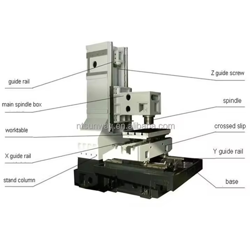
Every CNC machine, from the simplest 2-axis lathe to a full 5-Axis CNC Vertical Machining Center, is built on the same three-dimensional Cartesian coordinate foundation. These are the linear axes, and they describe straight-line travel in three perpendicular planes.
X-Axis: Left and Right Travel
The X-axis defines horizontal movement across the machine table — side to side, or left to right when viewed from the front of the machine. On a vertical machining center, the worktable or the column typically moves along this axis. The range of X travel is one of the primary specifications used to describe a machine's work envelope. A mid-size vertical machining center might offer 1,020 mm (approximately 40 inches) of X travel, while large gantry-style 5-axis platforms can exceed 3,000 mm.
Y-Axis: Front and Back Travel
The Y-axis is the other horizontal direction — front to back, or toward and away from the operator. Together with X, it forms the horizontal plane and allows the tool to reach any point on the flat surface of a workpiece. On most vertical machining centers, Y travel is somewhat shorter than X travel. A machine with 1,020 mm of X travel might offer 510 mm to 660 mm of Y travel, depending on the table configuration.
Z-Axis: Vertical Travel
The Z-axis is vertical movement — up and down. On a vertical machining center, the spindle moves along Z, plunging the cutting tool into the workpiece or retracting it. Z-axis depth of cut is closely tied to the rigidity of the machine spindle and the tool holder. In 3-Axis machining, all cutting happens through combinations of X, Y, and Z movement. The limitation is that the tool axis always remains parallel to Z, which makes it impossible to machine steep walls, undercuts, or compound angles without repositioning the part manually.
These three axes alone define what is called a 3-Axis machining center. For parts with features that can all be reached from the top — flat plates, simple pockets, through-holes, and 2D profiles — a 3-Axis machine is entirely sufficient. The moment a part requires machined surfaces at an angle, or features on multiple faces, the case for adding rotational axes becomes clear.
The Two Rotational Axes: A, B, and C
The fourth and fifth axes introduce rotation into the cutting envelope. Unlike X, Y, and Z, which describe linear displacement in millimeters or inches, rotational axes are measured in degrees. There are three possible rotational axes on a CNC machine — A, B, and C — but a 5-axis machine uses only two of them, depending on the machine's mechanical design.
A-Axis: Rotation Around X
The A-axis is rotation about the X-axis. Think of it as tilting forward and backward — like nodding. When the A-axis rotates, the workpiece or cutting head tilts in the plane that contains Y and Z. A-axis rotation is commonly found on trunnion-style 5-axis machines, where the worktable tilts to present the part at an angle to the stationary or repositioning spindle. A full-travel A-axis might rotate from -120° to +30°, or from 0° to 360° on a continuous rotary table.
B-Axis: Rotation Around Y
The B-axis is rotation about the Y-axis — tilting side to side, or in the XZ plane. On a 5-Axis CNC Vertical Machining Center with a swivel spindle head, the B-axis is often the axis that tilts the spindle itself, allowing it to approach the workpiece at compound angles. B-axis rotation is the foundation of fork-type or swivel-head 5-axis configurations, which are common in aerospace manufacturing where large structural panels need to be machined without flipping the part.
C-Axis: Rotation Around Z
The C-axis is rotation about the Z-axis — a spinning motion in the XY plane, like a lazy susan. On a 5-axis machine, the C-axis is commonly the rotary component of a trunnion table, allowing the workpiece to rotate 360° to present different faces to the spindle. On a mill-turn center, C-axis rotation combined with driven tooling is what makes it possible to mill flats, drill cross-holes, and cut splines on a turned part without moving it to a separate milling machine.
Most 5-axis machines use either an A+C combination (trunnion table with rotary) or a B+C combination (swivel head with rotary). The specific pairing depends on the machine type and the application. A+C trunnion configurations are popular for smaller precision parts because the table supports the workpiece rigidly. B+C or A+B head configurations tend to be preferred for larger workpieces that cannot be tilted on a table.
3-Axis vs 5-Axis: What the Extra Axes Actually Change
The difference between a 3-Axis and a 5-axis machine is not simply that one has more motors. The extra axes change what is physically possible to machine, how many setups are required, and what surface quality can be achieved.
| Capability | 3-Axis CNC | 5-Axis CNC Vertical Machining Center |
|---|---|---|
| Tool Approach Angles | Fixed, always parallel to Z | Variable, up to ±90° or more |
| Undercuts | Not possible without manual repositioning | Achievable in a single setup |
| Setups for Complex Parts | Often 5–10 or more | Often 1–2 |
| Surface Finish on Curved Surfaces | Step-overs visible; more handwork needed | Tangent tool contact; better finish with fewer passes |
| Tool Length in Tight Areas | Long tools required, more deflection | Short tools used at angle, better rigidity |
| Programming Complexity | Lower; standard CAM toolpaths | Higher; requires 5-axis CAM and post-processor |
| Typical Applications | Plates, brackets, prismatic parts | Impellers, turbine blades, molds, bone implants |
One of the most underappreciated advantages of 5-axis machining is the ability to use shorter cutting tools. On a 3-Axis machine, reaching a deep cavity or a steep wall requires a long end mill, which increases vibration and tool deflection, reduces cutting speeds, and worsens surface finish. On a 5-axis machine, the spindle can tilt and the part can be presented at an angle, so a shorter, stiffer tool reaches the same features. Shops running 5-axis equipment routinely report 30–50% reductions in cycle time on complex parts compared to 3-axis equivalents, not because the machine moves faster, but because fewer setups, shorter tools, and better cutter engagement all add up.
Indexed 5-Axis vs Simultaneous 5-Axis Machining
Owning a 5-axis machine does not automatically mean every operation uses all five axes at the same time. There are two fundamentally different ways the five axes are used, and understanding the distinction matters for programming, setup, and quoting.
3+2 Indexing (Positional 5-Axis)
In 3+2 machining, the two rotational axes are used to tilt the part or spindle to a fixed angle, and then the cutting is done using only the three linear axes. The rotational axes do not move during the cut — they hold position while X, Y, and Z do the work. This is sometimes called positional 5-axis or indexed 5-axis. It is the most common way 5-axis machines are used in job shops, because it dramatically reduces the number of fixturings and vise setups without requiring complex 5-axis CAM toolpaths. The control and programming demands are similar to 3-axis machining, just with an angular offset applied. An estimated 70–80% of parts machined on 5-axis equipment use 3+2 strategies for the majority of their features.
True Simultaneous 5-Axis
In simultaneous 5-axis machining, all five axes move at the same time, continuously adjusting the tool position and orientation as the tool traverses a curved surface. This is what is required for true freeform surfaces — the kind found on turbine blades, impeller vanes, progressive die faces, and orthopedic implants. The tool tip follows the surface while the tool axis tilts to maintain the optimal contact angle, minimizing scallop height and producing excellent surface finish without handpolishing. Simultaneous 5-axis requires sophisticated CAM software, careful post-processing, and a CNC controller capable of interpolating five axes smoothly. Machines used in demanding simultaneous 5-axis work typically feature high-speed direct-drive spindles in the 15,000 to 30,000 RPM range and linear scale feedback on all axes for closed-loop position accuracy.
Common 5-Axis Machine Configurations and Their Axis Assignments
Not every 5-axis machine implements the rotational axes in the same way. The mechanical configuration has a direct effect on work envelope, rigidity, and the types of parts the machine handles well.
Trunnion Table (A+C)
The most widely sold configuration for small-to-medium 5-axis vertical machining centers uses a trunnion table that tilts on the A-axis and rotates on the C-axis. The spindle is a conventional vertical spindle that only moves in X, Y, and Z. The workpiece is clamped to the rotary table, which sits on the trunnion cradle. This configuration is extremely rigid because the part is supported on both sides of the A-axis pivot. It is well-suited to compact aerospace components, medical devices, and precision mold inserts. The limitation is workpiece size and weight: a typical trunnion on a mid-size machine might accept workpieces up to 600 mm in diameter and 300 kg.
Swivel Head (B-axis) with Rotary Table (C-axis)
In this layout, the spindle tilts on the B-axis (rotation around Y), and a rotary table provides C-axis rotation. The workpiece sits on a conventional flat table or a rotary fixture. Because the spindle tilts rather than the workpiece, there is no restriction on workpiece weight due to rotation. This configuration is popular for large structural aerospace parts and long workpieces like extrusions and fuselage frames, where the part simply cannot be tilted on a table.
Fork-Type Swivel Head (A+B)
Some high-end 5-Axis CNC Vertical Machining Center designs move both rotational axes in the spindle head, with the spindle mounted in a fork that tilts on A and the entire fork assembly rotating on B. This places all the rotational motion in the head and allows the full table area to be used for large, heavy, or awkward workpieces. Fork heads can typically reach from vertical to horizontal and anywhere in between, giving essentially full hemisphere coverage of tool approach angle.
Gantry 5-Axis
For very large workpieces — wing spars, ship propellers, large mold bases — gantry-style 5-axis machines suspend the spindle head on a bridge that travels over a fixed or traveling table. The gantry provides X and Y travel often exceeding 5–10 meters, while Z travel is provided by the ram or quill. The rotational axes are built into the spindle head. These machines are less common in general job shops but are the backbone of aerospace structural manufacturing and heavy industry.
Industries and Parts That Drive 5-Axis Adoption
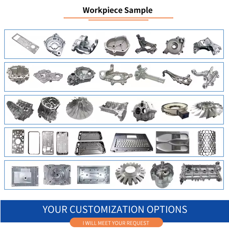
The decision to invest in a 5-axis vertical machining center is usually driven by specific part geometries and tolerance requirements. The following industries consistently generate work that is impractical or impossible to do on a 3-axis machine.
- Aerospace: Structural brackets with compound-angle holes, turbine blades with twisted airfoil sections, impellers with tight blade-to-blade clearances. Boeing, Airbus, and their suppliers rely on 5-axis machining for titanium and aluminum structural components where tolerances are often held to ±0.025 mm across complex surfaces.
- Medical: Orthopedic implants such as femoral knee components and spinal cages have smooth, anatomically contoured surfaces that must be free of machining marks to avoid stress risers in vivo. Dental milling of zirconia and cobalt-chrome prosthetics is almost entirely performed on 5-axis equipment.
- Automotive: Progressive die faces for body panels, intake manifold ports, cylinder head combustion chambers, and turbocharger compressor housings all benefit from 5-axis capability. High-performance racing component suppliers are particularly heavy users.
- Energy: Pump casings, impellers, and valve bodies for oil and gas applications often have complex internal passages. Wind turbine hub components and large gear housings in the power generation sector are also 5-axis candidates.
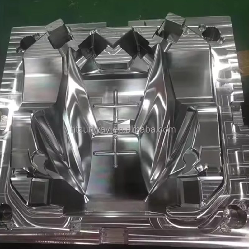
- Mold and Die: Deep-cavity injection molds, blow molds, and forging dies with curved parting lines benefit from 5-axis finishing passes that keep the tool short and the cutting forces consistent across the surface.
A concrete example from the aerospace sector: machining an aluminum structural rib with compound-angle flanges and lightening holes on a 3-axis machine requires the operator to machine one face, remove the part, build a custom angle-plate fixture, re-indicate the part, and machine the flange features — often four to six setups for a single part. On a 5-axis machine, the same rib can be completed in two setups (top and bottom), with all compound-angle features programmed directly into the 5-axis toolpath. Setup time drops from roughly four hours to under one hour, and the positional accuracy of CNC-indexed rotation is far more repeatable than manual re-fixturing.
Key Specifications to Evaluate on a 5-Axis CNC Vertical Machining Center
When comparing 5-axis machines, axis count is only the starting point. The specifications below determine whether a machine can handle the work you intend to run.
Rotary Axis Travel and Tilt Range
The angular range of the A and C (or B and C) axes determines which features are reachable without repositioning. A trunnion that tilts only from -30° to +110° is insufficient for machining the underside of a part in a single clamping. Continuous 360° C-axis rotation and at least ±90° or more of A-axis tilt covers the widest range of part geometries. Confirm whether the machine can hold position under cutting load at any angle, or whether it uses a locking mechanism that reduces axis stiffness while unlocked.
Rotary Axis Positioning Accuracy
The ISO 230-1 and ISO 230-7 standards define how rotary axis accuracy is measured. For precision work, angular positioning accuracy of ±3 arc-seconds or better is expected on quality 5-axis machines. Some high-end machines with direct-drive torque motors and angle encoders achieve ±1 arc-second. A 1 arc-second error at a 300 mm radius translates to a positional error of about 0.0015 mm — well within tolerance for most precision parts. Worm-gear-driven rotary axes with backlash compensation are less precise and are more appropriate for less demanding work.
Spindle Taper and Speed Range
Most 5-axis vertical machining centers use HSK-A63 or BT40/CAT40 tooling. HSK tooling is preferred for 5-axis work because its simultaneous face-and-taper contact provides higher rigidity and better runout — critical when the spindle is tilted and cutting forces act in unusual orientations. Spindle speeds of 12,000 to 24,000 RPM are common, with some high-speed aluminum machining spindles reaching 30,000 RPM or more.
CNC Controller and Kinematics Compensation
5-axis machining demands a controller capable of RTCP (Rotary Tool Center Point) compensation, sometimes called TCP or TCPM. This feature keeps the programmed tool tip at the correct position on the workpiece even as the rotational axes change angle, automatically compensating for the tool length offset in the new orientation. Without RTCP, every angle change requires the programmer to recalculate tool positions manually — effectively making simultaneous 5-axis machining unworkable. Fanuc 31i, Siemens 840D sl, Heidenhain TNC 640, and Mitsubishi M800 are the controllers most commonly found on quality 5-axis machines, all supporting RTCP.
Table Load Capacity and Work Envelope
The trunnion configuration inherently limits workpiece weight because the part rotates with the table. Mid-size 5-axis trunnion machines typically accept 200–500 kg on the rotary table. Exceeding this limit risks inaccuracy from deflection or axis drive overload. For heavier workpieces, a swivel-head configuration is more appropriate, since the table is fixed and the head rotates instead.
Programming Considerations for All Five Axes
Writing CNC programs for a 5-axis machine is substantially different from programming a 3-axis machining center. The additional axes introduce several programming challenges that require both the right software and a solid understanding of the machine's kinematics.
CAM Software Requirements
Not all CAM packages support true 5-axis toolpath generation. For 3+2 indexed work, most mid-range CAM systems (Mastercam, Fusion 360, SolidCAM) handle programming well. For simultaneous 5-axis surfaces — impellers, turbine blades, organic freeforms — packages like Siemens NX, Hypermill, Tebis, and Delcam PowerMILL are more commonly used in production environments due to their advanced surface following, lead/lag angle control, and gouge avoidance algorithms.
Post-Processor Accuracy
The post-processor translates the CAM toolpaths into machine-specific G-code that accounts for the kinematic configuration of the actual machine. A post-processor written for a Hermle C 400 trunnion machine cannot be used directly on a DMG Mori DMU 50 without modification, even though both are 5-axis machines. A poorly configured post-processor is the most common source of crashes and out-of-tolerance parts on 5-axis machines. Machine tool builders and experienced CAM resellers typically supply and validate post-processors for their supported machines.
Machine Simulation and Collision Detection
Because the tool can approach the workpiece from almost any direction on a 5-axis machine, the risk of the spindle housing, tool holder, or cutting tool colliding with the part, fixture, or table is significantly higher than on a 3-axis machine. Machine simulation in the CAM environment — using an accurate solid model of the machine, tool holders, fixtures, and workpiece — is not optional for 5-axis work; it is a standard step in the programming process. Software packages like VERICUT, NCSimul, and built-in simulation tools within CAM systems are used to verify that the entire program is collision-free before it runs on the machine.
When 5-Axis Is Worth the Investment — and When It Is Not
The purchase price of a quality 5-axis vertical machining center is typically two to four times that of an equivalent 3-axis machine. The additional cost is justified when the work demands it, but for shops running primarily prismatic or 2.5D parts, the economics of 3-axis machining remain strong.
5-axis investment is clearly justified when:
- Parts have compound-angle features, undercuts, or sculpted surfaces that require multiple manual setups on a 3-axis machine
- Workpiece material is expensive (titanium, Inconel, medical-grade stainless) and the cost of scrap from manual repositioning errors is high
- Part tolerances require better surface finish than 3-axis step-over patterns can achieve
- Production volumes are sufficient to amortize the higher machine cost and programming investment
- The shop is competing for aerospace, medical, or defense contracts where 5-axis capability is essentially required to quote
3-axis remains the better choice when:
- The majority of work consists of flat plates, simple pockets, and features accessible from one direction
- Part volumes are high and cycle times are short, making setup efficiency more important than setup reduction
- The shop does not have — and cannot easily hire — programmers with 5-axis CAM experience
- Capital budget is limited and a higher-quality 3-axis machine offers more immediate return than a lower-quality 5-axis machine
A practical middle ground that many shops adopt is purchasing a quality 3-Axis vertical machining center paired with a fourth-axis rotary table. This enables 4-axis indexed machining for a fraction of the cost of a full 5-axis machine, and covers a large percentage of parts that would otherwise require 5-axis capability — specifically those that need rotation to access multiple faces but do not require simultaneous 5-axis contouring.
Interested in cooperation or have questions?
News
-
-
An EDM machine, also called an electrical discharge machining machine, uses controlled sparks to erode electrically conductive metal without direct contact between the tool and the workpiece. The workpiece is submerged in a diele...
READ MORE -
Cutting Tools Are Used to Convert Raw Material into Functional Parts Cutting tools are the hardened, wear-resistant elements that shear away unwanted material from a workpiece to create a finished component. They are applied in e...
READ MORE -
A CNC machine can cut, drill, mill, turn, burn, and shape almost any conductive or composite material with an accuracy that manual machines rarely match. The real question is not what a CNC machine can do in theory, but what a sp...
READ MORE
Related Products

-
Factory Address
Zhaxi Township Industrial Park, Nantong City, Jiangsu Province, China (west of Huaneng Power Plant)
-
Phone
+86-13615235768
+86-15950816906
-
Fax
+86-513-85632766
-
Email
pan.director@sunwayer.com
Stay Connected
lf you can't find the answer you're looking for, chat with our friendly team.
Stay Connected
Copyright © Nantong Sunway Science and Technology Development Co., Ltd. All Rights Reserved.
China CNC Equipment Manufacturers
Custom CNC Equipment Factory
